Cooling of air in an enclosed space
This article is about cooling of air. For the Curved Air album, see Air Conditioning (album). For a similar device capable of both cooling and heating, see heat pump.
"a/c" redirects here. For the abbreviation used in banking and book-keeping, see Account (disambiguation). For other uses, see AC.
There are various types of air conditioners. Popular examples include: Window-mounted air conditioner (Suriname, 1955); Ceiling-mounted cassette air conditioner (China, 2023); Wall-mounted air conditioner (Japan, 2020); Ceiling-mounted console (Also called ceiling suspended) air conditioner (China, 2023); and portable air conditioner (Vatican City, 2018).
Air conditioning, often abbreviated as A/C (US) or air con (UK),[1] is the process of removing heat from an enclosed space to achieve a more comfortable interior temperature (sometimes referred to as 'comfort cooling') and in some cases also strictly controlling the humidity of internal air. Air conditioning can be achieved using a mechanical 'air conditioner' or by other methods, including passive cooling and ventilative cooling.[2][3] Air conditioning is a member of a family of systems and techniques that provide heating, ventilation, and air conditioning (HVAC).[4] Heat pumps are similar in many ways to air conditioners, but use a reversing valve to allow them both to heat and to cool an enclosed space.[5]
Air conditioners, which typically use vapor-compression refrigeration, range in size from small units used in vehicles or single rooms to massive units that can cool large buildings.[6] Air source heat pumps, which can be used for heating as well as cooling, are becoming increasingly common in cooler climates.
Air conditioners can reduce mortality rates due to higher temperature.[7] According to the International Energy Agency (IEA) 1.6 billion air conditioning units were used globally in 2016.[8] The United Nations called for the technology to be made more sustainable to mitigate climate change and for the use of alternatives, like passive cooling, evaporative cooling, selective shading, windcatchers, and better thermal insulation.
History
[edit]
Air conditioning dates back to prehistory.[9] Double-walled living quarters, with a gap between the two walls to encourage air flow, were found in the ancient city of Hamoukar, in modern Syria.[10] Ancient Egyptian buildings also used a wide variety of passive air-conditioning techniques.[11] These became widespread from the Iberian Peninsula through North Africa, the Middle East, and Northern India.[12]
Passive techniques remained widespread until the 20th century when they fell out of fashion and were replaced by powered air conditioning. Using information from engineering studies of traditional buildings, passive techniques are being revived and modified for 21st-century architectural designs.[13][12]
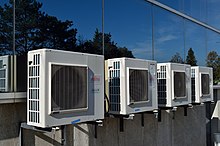 An array of air conditioner condenser units outside a commercial office building
Air conditioners allow the building's indoor environment to remain relatively constant, largely independent of changes in external weather conditions and internal heat loads. They also enable deep plan buildings to be created and have allowed people to live comfortably in hotter parts of the world.[14]
Development
[edit]
Preceding discoveries
[edit]
In 1558, Giambattista della Porta described a method of chilling ice to temperatures far below its freezing point by mixing it with potassium nitrate (then called "nitre") in his popular science book Natural Magic.[15][16][17] In 1620, Cornelis Drebbel demonstrated "Turning Summer into Winter" for James I of England, chilling part of the Great Hall of Westminster Abbey with an apparatus of troughs and vats.[18] Drebbel's contemporary Francis Bacon, like della Porta a believer in science communication, may not have been present at the demonstration, but in a book published later the same year, he described it as "experiment of artificial freezing" and said that "Nitre (or rather its spirit) is very cold, and hence nitre or salt when added to snow or ice intensifies the cold of the latter, the nitre by adding to its cold, but the salt by supplying activity to the cold of the snow."[15]
In 1758, Benjamin Franklin and John Hadley, a chemistry professor at the University of Cambridge, conducted experiments applying the principle of evaporation as a means to cool an object rapidly. Franklin and Hadley confirmed that the evaporation of highly volatile liquids (such as alcohol and ether) could be used to drive down the temperature of an object past the freezing point of water. They experimented with the bulb of a mercury-in-glass thermometer as their object. They used a bellows to speed up the evaporation. They lowered the temperature of the thermometer bulb down to −14 °C (7 °F) while the ambient temperature was 18 °C (64 °F). Franklin noted that soon after they passed the freezing point of water 0 °C (32 °F), a thin film of ice formed on the surface of the thermometer's bulb and that the ice mass was about
6 mm (1⁄4 in) thick when they stopped the experiment upon reaching −14 °C (7 °F). Franklin concluded: "From this experiment, one may see the possibility of freezing a man to death on a warm summer's day."[19]
The 19th century included many developments in compression technology. In 1820, English scientist and inventor Michael Faraday discovered that compressing and liquefying ammonia could chill air when the liquefied ammonia was allowed to evaporate.[20] In 1842, Florida physician John Gorrie used compressor technology to create ice, which he used to cool air for his patients in his hospital in Apalachicola, Florida. He hoped to eventually use his ice-making machine to regulate the temperature of buildings.[20][21] He envisioned centralized air conditioning that could cool entire cities. Gorrie was granted a patent in 1851,[22] but following the death of his main backer, he was not able to realize his invention.[23] In 1851, James Harrison created the first mechanical ice-making machine in Geelong, Australia, and was granted a patent for an ether vapor-compression refrigeration system in 1855 that produced three tons of ice per day.[24] In 1860, Harrison established a second ice company. He later entered the debate over competing against the American advantage of ice-refrigerated beef sales to the United Kingdom.[24]
First devices
[edit]
 Willis Carrier, who is credited with building the first modern electrical air conditioning unit
Electricity made the development of effective units possible. In 1901, American inventor Willis H. Carrier built what is considered the first modern electrical air conditioning unit.[25][26][27][28] In 1902, he installed his first air-conditioning system, in the Sackett-Wilhelms Lithographing & Publishing Company in Brooklyn, New York.[29] His invention controlled both the temperature and humidity, which helped maintain consistent paper dimensions and ink alignment at the printing plant. Later, together with six other employees, Carrier formed The Carrier Air Conditioning Company of America, a business that in 2020 employed 53,000 people and was valued at $18.6 billion.[30][31]
In 1906, Stuart W. Cramer of Charlotte, North Carolina, was exploring ways to add moisture to the air in his textile mill. Cramer coined the term "air conditioning" in a patent claim which he filed that year, where he suggested that air conditioning was analogous to "water conditioning", then a well-known process for making textiles easier to process.[32] He combined moisture with ventilation to "condition" and change the air in the factories; thus, controlling the humidity that is necessary in textile plants. Willis Carrier adopted the term and incorporated it into the name of his company.[33]
Domestic air conditioning soon took off. In 1914, the first domestic air conditioning was installed in Minneapolis in the home of Charles Gilbert Gates. It is, however, possible that the considerable device (c. 2.1 m × 1.8 m × 6.1 m; 7 ft × 6 ft × 20 ft) was never used, as the house remained uninhabited[20] (Gates had already died in October 1913.)
In 1931, H.H. Schultz and J.Q. Sherman developed what would become the most common type of individual room air conditioner: one designed to sit on a window ledge. The units went on sale in 1932 at US$10,000 to $50,000 (the equivalent of $200,000 to $1,100,000 in 2023.)[20] A year later, the first air conditioning systems for cars were offered for sale.[34] Chrysler Motors introduced the first practical semi-portable air conditioning unit in 1935,[35] and Packard became the first automobile manufacturer to offer an air conditioning unit in its cars in 1939.[36]
Further development
[edit]
Innovations in the latter half of the 20th century allowed more ubiquitous air conditioner use. In 1945, Robert Sherman of Lynn, Massachusetts, invented a portable, in-window air conditioner that cooled, heated, humidified, dehumidified, and filtered the air.[37] The first inverter air conditioners were released in 1980–1981.[38][39]
In 1954, Ned Cole, a 1939 architecture graduate from the University of Texas at Austin, developed the first experimental "suburb" with inbuilt air conditioning in each house. 22 homes were developed on a flat, treeless track in northwest Austin, Texas, and the community was christened the 'Austin Air-Conditioned Village.' The residents were subjected to a year-long study of the effects of air conditioning led by the nation’s premier air conditioning companies, builders, and social scientists. In addition, researchers from UT’s Health Service and Psychology Department studied the effects on the "artificially cooled humans." One of the more amusing discoveries was that each family reported being troubled with scorpions, the leading theory being that scorpions sought cool, shady places. Other reported changes in lifestyle were that mothers baked more, families ate heavier foods, and they were more apt to choose hot drinks.[40][41]
Air conditioner adoption tends to increase above around $10,000 annual household income in warmer areas.[42] Global GDP growth explains around 85% of increased air condition adoption by 2050, while the remaining 15% can be explained by climate change.[42]
As of 2016 an estimated 1.6 billion air conditioning units were used worldwide, with over half of them in China and USA, and a total cooling capacity of 11,675 gigawatts.[8][43] The International Energy Agency predicted in 2018 that the number of air conditioning units would grow to around 4 billion units by 2050 and that the total cooling capacity would grow to around 23,000 GW, with the biggest increases in India and China.[8] Between 1995 and 2004, the proportion of urban households in China with air conditioners increased from 8% to 70%.[44] As of 2015, nearly 100 million homes, or about 87% of US households, had air conditioning systems.[45] In 2019, it was estimated that 90% of new single-family homes constructed in the US included air conditioning (ranging from 99% in the South to 62% in the West).[46][47]
Operation
[edit]
Operating principles
[edit]
Main article: Vapor-compression refrigeration
 A simple stylized diagram of the refrigeration cycle: 1) condensing coil, 2) expansion valve, 3) evaporator coil, 4) compressor
Cooling in traditional air conditioner systems is accomplished using the vapor-compression cycle, which uses a refrigerant's forced circulation and phase change between gas and liquid to transfer heat.[48][49] The vapor-compression cycle can occur within a unitary, or packaged piece of equipment; or within a chiller that is connected to terminal cooling equipment (such as a fan coil unit in an air handler) on its evaporator side and heat rejection equipment such as a cooling tower on its condenser side. An air source heat pump shares many components with an air conditioning system, but includes a reversing valve, which allows the unit to be used to heat as well as cool a space.[50]
Air conditioning equipment will reduce the absolute humidity of the air processed by the system if the surface of the evaporator coil is significantly cooler than the dew point of the surrounding air. An air conditioner designed for an occupied space will typically achieve a 30% to 60% relative humidity in the occupied space.[51]
Most modern air-conditioning systems feature a dehumidification cycle during which the compressor runs. At the same time, the fan is slowed to reduce the evaporator temperature and condense more water. A dehumidifier uses the same refrigeration cycle but incorporates both the evaporator and the condenser into the same air path; the air first passes over the evaporator coil, where it is cooled[52] and dehumidified before passing over the condenser coil, where it is warmed again before it is released back into the room.[citation needed]
Free cooling can sometimes be selected when the external air is cooler than the internal air. Therefore, the compressor does not need to be used, resulting in high cooling efficiencies for these times. This may also be combined with seasonal thermal energy storage.[53]
Heating
[edit]
Main article: Heat pump
Some air conditioning systems can reverse the refrigeration cycle and act as an air source heat pump, thus heating instead of cooling the indoor environment. They are also commonly referred to as "reverse cycle air conditioners". The heat pump is significantly more energy-efficient than electric resistance heating, because it moves energy from air or groundwater to the heated space and the heat from purchased electrical energy. When the heat pump is in heating mode, the indoor evaporator coil switches roles and becomes the condenser coil, producing heat. The outdoor condenser unit also switches roles to serve as the evaporator and discharges cold air (colder than the ambient outdoor air).
Most air source heat pumps become less efficient in outdoor temperatures lower than 4 °C or 40 °F.[54] This is partly because ice forms on the outdoor unit's heat exchanger coil, which blocks air flow over the coil. To compensate for this, the heat pump system must temporarily switch back into the regular air conditioning mode to switch the outdoor evaporator coil back to the condenser coil, to heat up and defrost. Therefore, some heat pump systems will have electric resistance heating in the indoor air path that is activated only in this mode to compensate for the temporary indoor air cooling, which would otherwise be uncomfortable in the winter.
Newer models have improved cold-weather performance, with efficient heating capacity down to −14 °F (−26 °C).[55][54][56] However, there is always a chance that the humidity that condenses on the heat exchanger of the outdoor unit could freeze, even in models that have improved cold-weather performance, requiring a defrosting cycle to be performed.
The icing problem becomes much more severe with lower outdoor temperatures, so heat pumps are sometimes installed in tandem with a more conventional form of heating, such as an electrical heater, a natural gas, heating oil, or wood-burning fireplace or central heating, which is used instead of or in addition to the heat pump during harsher winter temperatures. In this case, the heat pump is used efficiently during milder temperatures, and the system is switched to the conventional heat source when the outdoor temperature is lower.
[edit]
Main articles: coefficient of performance, Seasonal energy efficiency ratio, and European seasonal energy efficiency ratio
The coefficient of performance (COP) of an air conditioning system is a ratio of useful heating or cooling provided to the work required.[57][58] Higher COPs equate to lower operating costs. The COP usually exceeds 1; however, the exact value is highly dependent on operating conditions, especially absolute temperature and relative temperature between sink and system, and is often graphed or averaged against expected conditions.[59] Air conditioner equipment power in the U.S. is often described in terms of "tons of refrigeration", with each approximately equal to the cooling power of one short ton (2,000 pounds (910 kg) of ice melting in a 24-hour period. The value is equal to 12,000 BTUIT per hour, or 3,517 watts.[60] Residential central air systems are usually from 1 to 5 tons (3.5 to 18 kW) in capacity.[citation needed]
The efficiency of air conditioners is often rated by the seasonal energy efficiency ratio (SEER), which is defined by the Air Conditioning, Heating and Refrigeration Institute in its 2008 standard AHRI 210/240, Performance Rating of Unitary Air-Conditioning and Air-Source Heat Pump Equipment.[61] A similar standard is the European seasonal energy efficiency ratio (ESEER).[citation needed]
Efficiency is strongly affected by the humidity of the air to be cooled. Dehumidifying the air before attempting to cool it can reduce subsequent cooling costs by as much as 90 percent. Thus, reducing dehumidifying costs can materially affect overall air conditioning costs.[62]
Control system
[edit]
Wireless remote control
[edit]
Main articles: Remote control and Infrared blaster
A wireless remote controller
The infrared transmitting LED on the remote
The infrared receiver on the air conditioner
This type of controller uses an infrared LED to relay commands from a remote control to the air conditioner. The output of the infrared LED (like that of any infrared remote) is invisible to the human eye because its wavelength is beyond the range of visible light (940 nm). This system is commonly used on mini-split air conditioners because it is simple and portable. Some window and ducted central air conditioners uses it as well.
Wired controller
[edit]
Main article: Thermostat
Several wired controllers (Indonesia, 2024)
A wired controller, also called a "wired thermostat," is a device that controls an air conditioner by switching heating or cooling on or off. It uses different sensors to measure temperatures and actuate control operations. Mechanical thermostats commonly use bimetallic strips, converting a temperature change into mechanical displacement, to actuate control of the air conditioner. Electronic thermostats, instead, use a thermistor or other semiconductor sensor, processing temperature change as electronic signals to control the air conditioner.
These controllers are usually used in hotel rooms because they are permanently installed into a wall and hard-wired directly into the air conditioner unit, eliminating the need for batteries.
Types
[edit]
| Types |
Typical Capacity* |
Air supply |
Mounting |
Typical application |
| Mini-split |
small – large |
Direct |
Wall |
Residential |
| Window |
very small – small |
Direct |
Window |
Residential |
| Portable |
very small – small |
Direct / Ducted |
Floor |
Residential, remote areas |
| Ducted (individual) |
small – very large |
Ducted |
Ceiling |
Residential, commercial |
| Ducted (central) |
medium – very large |
Ducted |
Ceiling |
Residential, commercial |
| Ceiling suspended |
medium – large |
Direct |
Ceiling |
Commercial |
| Cassette |
medium – large |
Direct / Ducted |
Ceiling |
Commercial |
| Floor standing |
medium – large |
Direct / Ducted |
Floor |
Commercial |
| Packaged |
very large |
Direct / Ducted |
Floor |
Commercial |
| Packaged RTU (Rooftop Unit) |
very large |
Ducted |
Rooftop |
Commercial |
* where the typical capacity is in kilowatt as follows:
- very small: <1.5 kW
- small: 1.5–3.5 kW
- medium: 4.2–7.1 kW
- large: 7.2–14 kW
- very large: >14 kW
Mini-split and multi-split systems
[edit]
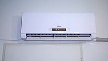 Evaporator, indoor unit, or terminal, side of a ductless split-type air conditioner
Ductless systems (often mini-split, though there are now ducted mini-split) typically supply conditioned and heated air to a single or a few rooms of a building, without ducts and in a decentralized manner.[63] Multi-zone or multi-split systems are a common application of ductless systems and allow up to eight rooms (zones or locations) to be conditioned independently from each other, each with its indoor unit and simultaneously from a single outdoor unit.
The first mini-split system was sold in 1961 by Toshiba in Japan, and the first wall-mounted mini-split air conditioner was sold in 1968 in Japan by Mitsubishi Electric, where small home sizes motivated their development. The Mitsubishi model was the first air conditioner with a cross-flow fan.[64][65][66] In 1969, the first mini-split air conditioner was sold in the US.[67] Multi-zone ductless systems were invented by Daikin in 1973, and variable refrigerant flow systems (which can be thought of as larger multi-split systems) were also invented by Daikin in 1982. Both were first sold in Japan.[68] Variable refrigerant flow systems when compared with central plant cooling from an air handler, eliminate the need for large cool air ducts, air handlers, and chillers; instead cool refrigerant is transported through much smaller pipes to the indoor units in the spaces to be conditioned, thus allowing for less space above dropped ceilings and a lower structural impact, while also allowing for more individual and independent temperature control of spaces. The outdoor and indoor units can be spread across the building.[69] Variable refrigerant flow indoor units can also be turned off individually in unused spaces.[citation needed] The lower start-up power of VRF's DC inverter compressors and their inherent DC power requirements also allow VRF solar-powered heat pumps to be run using DC-providing solar panels.
Ducted central systems
[edit]
Split-system central air conditioners consist of two heat exchangers, an outside unit (the condenser) from which heat is rejected to the environment and an internal heat exchanger (the evaporator, or Fan Coil Unit, FCU) with the piped refrigerant being circulated between the two. The FCU is then connected to the spaces to be cooled by ventilation ducts.[70] Floor standing air conditioners are similar to this type of air conditioner but sit within spaces that need cooling.
Central plant cooling
[edit]
See also: Chiller
 Industrial air conditioners on top of the shopping mall Passage in Linz, Austria
Large central cooling plants may use intermediate coolant such as chilled water pumped into air handlers or fan coil units near or in the spaces to be cooled which then duct or deliver cold air into the spaces to be conditioned, rather than ducting cold air directly to these spaces from the plant, which is not done due to the low density and heat capacity of air, which would require impractically large ducts. The chilled water is cooled by chillers in the plant, which uses a refrigeration cycle to cool water, often transferring its heat to the atmosphere even in liquid-cooled chillers through the use of cooling towers. Chillers may be air- or liquid-cooled.[71][72]
Portable units
[edit]
A portable system has an indoor unit on wheels connected to an outdoor unit via flexible pipes, similar to a permanently fixed installed unit (such as a ductless split air conditioner).
Hose systems, which can be monoblock or air-to-air, are vented to the outside via air ducts. The monoblock type collects the water in a bucket or tray and stops when full. The air-to-air type re-evaporates the water, discharges it through the ducted hose, and can run continuously. Many but not all portable units draw indoor air and expel it outdoors through a single duct, negatively impacting their overall cooling efficiency.
Many portable air conditioners come with heat as well as a dehumidification function.[73]
Window unit and packaged terminal
[edit]
 Through-the-wall PTAC units, University Motor Inn, Philadelphia
Main article: Packaged terminal air conditioner
The packaged terminal air conditioner (PTAC), through-the-wall, and window air conditioners are similar. These units are installed on a window frame or on a wall opening. The unit usually has an internal partition separating its indoor and outdoor sides, which contain the unit's condenser and evaporator, respectively. PTAC systems may be adapted to provide heating in cold weather, either directly by using an electric strip, gas, or other heaters, or by reversing the refrigerant flow to heat the interior and draw heat from the exterior air, converting the air conditioner into a heat pump. They may be installed in a wall opening with the help of a special sleeve on the wall and a custom grill that is flush with the wall and window air conditioners can also be installed in a window, but without a custom grill.[74]
Packaged air conditioner
[edit]
Packaged air conditioners (also known as self-contained units)[75][76] are central systems that integrate into a single housing all the components of a split central system, and deliver air, possibly through ducts, to the spaces to be cooled. Depending on their construction they may be outdoors or indoors, on roofs (rooftop units),[77][78] draw the air to be conditioned from inside or outside a building and be water or air-cooled. Often, outdoor units are air-cooled while indoor units are liquid-cooled using a cooling tower.[70][79][80][81][82][83]
Types of compressors
[edit]
| Compressor types |
Common applications |
Typical capacity |
Efficiency |
Durability |
Repairability |
| Reciprocating |
Refrigerator, Walk-in freezer, portable air conditioners |
small – large |
very low (small capacity)
medium (large capacity)
|
very low |
medium |
| Rotary vane |
Residential mini splits |
small |
low |
low |
easy |
| Scroll |
Commercial and central systems, VRF |
medium |
medium |
medium |
easy |
| Rotary screw |
Commercial chiller |
medium – large |
medium |
medium |
hard |
| Centrifugal |
Commercial chiller |
very large |
medium |
high |
hard |
| Maglev Centrifugal |
Commercial chiller |
very large |
high |
very high |
very hard |
Reciprocating
[edit]
-
Main article: Reciprocating compressor
This compressor consists of a crankcase, crankshaft, piston rod, piston, piston ring, cylinder head and valves. [citation needed]
[edit]
-
Main article: Scroll compressor
This compressor uses two interleaving scrolls to compress the refrigerant.[84] it consists of one fixed and one orbiting scrolls. This type of compressor is more efficient because it has 70 percent less moving parts than a reciprocating compressor. [citation needed]
Screw
[edit]
Main article: Rotary-screw compressor
This compressor use two very closely meshing spiral rotors to compress the gas. The gas enters at the suction side and moves through the threads as the screws rotate. The meshing rotors force the gas through the compressor, and the gas exits at the end of the screws. The working area is the inter-lobe volume between the male and female rotors. It is larger at the intake end, and decreases along the length of the rotors until the exhaust port. This change in volume is the compression. [citation needed]
Capacity modulation technologies
[edit]
There are several ways to modulate the cooling capacity in refrigeration or air conditioning and heating systems. The most common in air conditioning are: on-off cycling, hot gas bypass, use or not of liquid injection, manifold configurations of multiple compressors, mechanical modulation (also called digital), and inverter technology. [citation needed]
Hot gas bypass
[edit]
Hot gas bypass involves injecting a quantity of gas from discharge to the suction side. The compressor will keep operating at the same speed, but due to the bypass, the refrigerant mass flow circulating with the system is reduced, and thus the cooling capacity. This naturally causes the compressor to run uselessly during the periods when the bypass is operating. The turn down capacity varies between 0 and 100%.[85]
Manifold configurations
[edit]
Several compressors can be installed in the system to provide the peak cooling capacity. Each compressor can run or not in order to stage the cooling capacity of the unit. The turn down capacity is either 0/33/66 or 100% for a trio configuration and either 0/50 or 100% for a tandem.[citation needed]
Mechanically modulated compressor
[edit]
This internal mechanical capacity modulation is based on periodic compression process with a control valve, the two scroll set move apart stopping the compression for a given time period. This method varies refrigerant flow by changing the average time of compression, but not the actual speed of the motor. Despite an excellent turndown ratio – from 10 to 100% of the cooling capacity, mechanically modulated scrolls have high energy consumption as the motor continuously runs.[citation needed]
Variable-speed compressor
[edit]
-
Main article: Inverter compressor
This system uses a variable-frequency drive (also called an Inverter) to control the speed of the compressor. The refrigerant flow rate is changed by the change in the speed of the compressor. The turn down ratio depends on the system configuration and manufacturer. It modulates from 15 or 25% up to 100% at full capacity with a single inverter from 12 to 100% with a hybrid tandem. This method is the most efficient way to modulate an air conditioner's capacity. It is up to 58% more efficient than a fixed speed system.[citation needed]
Impact
[edit]
Health effects
[edit]
 Rooftop condenser unit fitted on top of an Osaka Municipal Subway 10 series subway carriage. Air conditioning has become increasingly prevalent on public transport vehicles as a form of climate control, and to ensure passenger comfort and drivers' occupational safety and health.
In hot weather, air conditioning can prevent heat stroke, dehydration due to excessive sweating, electrolyte imbalance, kidney failure, and other issues due to hyperthermia.[8][86] Heat waves are the most lethal type of weather phenomenon in the United States.[87][88] A 2020 study found that areas with lower use of air conditioning correlated with higher rates of heat-related mortality and hospitalizations.[89] The August 2003 France heatwave resulted in approximately 15,000 deaths, where 80% of the victims were over 75 years old. In response, the French government required all retirement homes to have at least one air-conditioned room at 25 °C (77 °F) per floor during heatwaves.[8]
Air conditioning (including filtration, humidification, cooling and disinfection) can be used to provide a clean, safe, hypoallergenic atmosphere in hospital operating rooms and other environments where proper atmosphere is critical to patient safety and well-being. It is sometimes recommended for home use by people with allergies, especially mold.[90][91] However, poorly maintained water cooling towers can promote the growth and spread of microorganisms such as Legionella pneumophila, the infectious agent responsible for Legionnaires' disease. As long as the cooling tower is kept clean (usually by means of a chlorine treatment), these health hazards can be avoided or reduced. The state of New York has codified requirements for registration, maintenance, and testing of cooling towers to protect against Legionella.[92]
Economic effects
[edit]
First designed to benefit targeted industries such as the press as well as large factories, the invention quickly spread to public agencies and administrations with studies with claims of increased productivity close to 24% in places equipped with air conditioning.[93]
Air conditioning caused various shifts in demography, notably that of the United States starting from the 1970s. In the US, the birth rate was lower in the spring than during other seasons until the 1970s but this difference then declined since then.[94] As of 2007, the Sun Belt contained 30% of the total US population while it was inhabited by 24% of Americans at the beginning of the 20th century.[95] Moreover, the summer mortality rate in the US, which had been higher in regions subject to a heat wave during the summer, also evened out.[7]
The spread of the use of air conditioning acts as a main driver for the growth of global demand of electricity.[96] According to a 2018 report from the International Energy Agency (IEA), it was revealed that the energy consumption for cooling in the United States, involving 328 million Americans, surpasses the combined energy consumption of 4.4 billion people in Africa, Latin America, the Middle East, and Asia (excluding China).[8] A 2020 survey found that an estimated 88% of all US households use AC, increasing to 93% when solely looking at homes built between 2010 and 2020.[97]
Environmental effects
[edit]
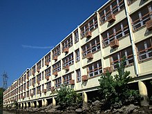
 Air conditioner farm in the facade of a building in Singapore
Space cooling including air conditioning accounted globally for 2021 terawatt-hours of energy usage in 2016 with around 99% in the form of electricity, according to a 2018 report on air-conditioning efficiency by the International Energy Agency.[8] The report predicts an increase of electricity usage due to space cooling to around 6200 TWh by 2050,[8][98] and that with the progress currently seen, greenhouse gas emissions attributable to space cooling will double: 1,135 million tons (2016) to 2,070 million tons.[8] There is some push to increase the energy efficiency of air conditioners. United Nations Environment Programme (UNEP) and the IEA found that if air conditioners could be twice as effective as now, 460 billion tons of GHG could be cut over 40 years.[99] The UNEP and IEA also recommended legislation to decrease the use of hydrofluorocarbons, better building insulation, and more sustainable temperature-controlled food supply chains going forward.[99]
Refrigerants have also caused and continue to cause serious environmental issues, including ozone depletion and climate change, as several countries have not yet ratified the Kigali Amendment to reduce the consumption and production of hydrofluorocarbons.[100] CFCs and HCFCs refrigerants such as R-12 and R-22, respectively, used within air conditioners have caused damage to the ozone layer,[101] and hydrofluorocarbon refrigerants such as R-410A and R-404A, which were designed to replace CFCs and HCFCs, are instead exacerbating climate change.[102] Both issues happen due to the venting of refrigerant to the atmosphere, such as during repairs. HFO refrigerants, used in some if not most new equipment, solve both issues with an ozone damage potential (ODP) of zero and a much lower global warming potential (GWP) in the single or double digits vs. the three or four digits of hydrofluorocarbons.[103]
Hydrofluorocarbons would have raised global temperatures by around 0.3–0.5 °C (0.5–0.9 °F) by 2100 without the Kigali Amendment. With the Kigali Amendment, the increase of global temperatures by 2100 due to hydrofluorocarbons is predicted to be around 0.06 °C (0.1 °F).[104]
Alternatives to continual air conditioning include passive cooling, passive solar cooling, natural ventilation, operating shades to reduce solar gain, using trees, architectural shades, windows (and using window coatings) to reduce solar gain.[citation needed]
Social effects
[edit]
Socioeconomic groups with a household income below around $10,000 tend to have a low air conditioning adoption,[42] which worsens heat-related mortality.[7] The lack of cooling can be hazardous, as areas with lower use of air conditioning correlate with higher rates of heat-related mortality and hospitalizations.[89] Premature mortality in NYC is projected to grow between 47% and 95% in 30 years, with lower-income and vulnerable populations most at risk.[89] Studies on the correlation between heat-related mortality and hospitalizations and living in low socioeconomic locations can be traced in Phoenix, Arizona,[105] Hong Kong,[106] China,[106] Japan,[107] and Italy.[108][109] Additionally, costs concerning health care can act as another barrier, as the lack of private health insurance during a 2009 heat wave in Australia, was associated with heat-related hospitalization.[109]
Disparities in socioeconomic status and access to air conditioning are connected by some to institutionalized racism, which leads to the association of specific marginalized communities with lower economic status, poorer health, residing in hotter neighborhoods, engaging in physically demanding labor, and experiencing limited access to cooling technologies such as air conditioning.[109] A study overlooking Chicago, Illinois, Detroit, and Michigan found that black households were half as likely to have central air conditioning units when compared to their white counterparts.[110] Especially in cities, Redlining creates heat islands, increasing temperatures in certain parts of the city.[109] This is due to materials heat-absorbing building materials and pavements and lack of vegetation and shade coverage.[111] There have been initiatives that provide cooling solutions to low-income communities, such as public cooling spaces.[8][111]
Other techniques
[edit]
Buildings designed with passive air conditioning are generally less expensive to construct and maintain than buildings with conventional HVAC systems with lower energy demands.[112] While tens of air changes per hour, and cooling of tens of degrees, can be achieved with passive methods, site-specific microclimate must be taken into account, complicating building design.[12]
Many techniques can be used to increase comfort and reduce the temperature in buildings. These include evaporative cooling, selective shading, wind, thermal convection, and heat storage.[113]
Passive ventilation
[edit]
This section is an excerpt from Passive ventilation.[edit]
 The ventilation system of a regular earthship
 Dogtrot houses are designed to maximise natural ventilation.
 A roof turbine ventilator, colloquially known as a 'Whirly Bird' is an application of wind driven ventilation.
Passive ventilation is the process of supplying air to and removing air from an indoor space without using mechanical systems. It refers to the flow of external air to an indoor space as a result of pressure differences arising from natural forces.
There are two types of natural ventilation occurring in buildings: wind driven ventilation and buoyancy-driven ventilation. Wind driven ventilation arises from the different pressures created by wind around a building or structure, and openings being formed on the perimeter which then permit flow through the building. Buoyancy-driven ventilation occurs as a result of the directional buoyancy force that results from temperature differences between the interior and exterior.[114]
Since the internal heat gains which create temperature differences between the interior and exterior are created by natural processes, including the heat from people, and wind effects are variable, naturally ventilated buildings are sometimes called "breathing buildings".
Passive cooling
[edit]
This section is an excerpt from Passive cooling.[edit]
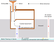 A traditional Iranian solar cooling design using a wind tower
Passive cooling is a building design approach that focuses on heat gain control and heat dissipation in a building in order to improve the indoor thermal comfort with low or no energy consumption.[115][116] This approach works either by preventing heat from entering the interior (heat gain prevention) or by removing heat from the building (natural cooling).[117]
Natural cooling utilizes on-site energy, available from the natural environment, combined with the architectural design of building components (e.g. building envelope), rather than mechanical systems to dissipate heat.[118] Therefore, natural cooling depends not only on the architectural design of the building but on how the site's natural resources are used as heat sinks (i.e. everything that absorbs or dissipates heat). Examples of on-site heat sinks are the upper atmosphere (night sky), the outdoor air (wind), and the earth/soil.
Passive cooling is an important tool for design of buildings for climate change adaptation – reducing dependency on energy-intensive air conditioning in warming environments.
[119][120]
 A pair of short windcatchers (malqaf) used in traditional architecture; wind is forced down on the windward side and leaves on the leeward side (cross-ventilation). In the absence of wind, the circulation can be driven with evaporative cooling in the inlet (which is also designed to catch dust). In the center, a shuksheika (roof lantern vent), used to shade the qa'a below while allowing hot air rise out of it (stack effect).[11]
Daytime radiative cooling
[edit]
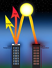 Passive daytime radiative cooling (PDRC) surfaces are high in solar reflectance and heat emittance, cooling with zero energy use or pollution.[121]
Passive daytime radiative cooling (PDRC) surfaces reflect incoming solar radiation and heat back into outer space through the infrared window for cooling during the daytime. Daytime radiative cooling became possible with the ability to suppress solar heating using photonic structures, which emerged through a study by Raman et al. (2014).[122] PDRCs can come in a variety of forms, including paint coatings and films, that are designed to be high in solar reflectance and thermal emittance.[121][123]
PDRC applications on building roofs and envelopes have demonstrated significant decreases in energy consumption and costs.[123] In suburban single-family residential areas, PDRC application on roofs can potentially lower energy costs by 26% to 46%.[124] PDRCs are predicted to show a market size of ~$27 billion for indoor space cooling by 2025 and have undergone a surge in research and development since the 2010s.[125][126]
Fans
[edit]
Main article: Ceiling fan
Hand fans have existed since prehistory. Large human-powered fans built into buildings include the punkah.
The 2nd-century Chinese inventor Ding Huan of the Han dynasty invented a rotary fan for air conditioning, with seven wheels 3 m (10 ft) in diameter and manually powered by prisoners.[127]: 99, 151, 233  In 747, Emperor Xuanzong (r. 712–762) of the Tang dynasty (618–907) had the Cool Hall (Liang Dian 涼殿) built in the imperial palace, which the Tang Yulin describes as having water-powered fan wheels for air conditioning as well as rising jet streams of water from fountains. During the subsequent Song dynasty (960–1279), written sources mentioned the air conditioning rotary fan as even more widely used.[127]: 134, 151 
Thermal buffering
[edit]
In areas that are cold at night or in winter, heat storage is used. Heat may be stored in earth or masonry; air is drawn past the masonry to heat or cool it.[13]
In areas that are below freezing at night in winter, snow and ice can be collected and stored in ice houses for later use in cooling.[13] This technique is over 3,700 years old in the Middle East.[128] Harvesting outdoor ice during winter and transporting and storing for use in summer was practiced by wealthy Europeans in the early 1600s,[15] and became popular in Europe and the Americas towards the end of the 1600s.[129] This practice was replaced by mechanical compression-cycle icemakers.
Evaporative cooling
[edit]
Main article: Evaporative cooler
 An evaporative cooler
In dry, hot climates, the evaporative cooling effect may be used by placing water at the air intake, such that the draft draws air over water and then into the house. For this reason, it is sometimes said that the fountain, in the architecture of hot, arid climates, is like the fireplace in the architecture of cold climates.[11] Evaporative cooling also makes the air more humid, which can be beneficial in a dry desert climate.[130]
Evaporative coolers tend to feel as if they are not working during times of high humidity, when there is not much dry air with which the coolers can work to make the air as cool as possible for dwelling occupants. Unlike other types of air conditioners, evaporative coolers rely on the outside air to be channeled through cooler pads that cool the air before it reaches the inside of a house through its air duct system; this cooled outside air must be allowed to push the warmer air within the house out through an exhaust opening such as an open door or window.[131]
See also
[edit]
- Air filter
- Air purifier
- Cleanroom
- Crankcase heater
- Energy recovery ventilation
- Indoor air quality
- Particulates
References
[edit]
- ^
"Air Con". Cambridge Dictionary. Archived from the original on May 3, 2022. Retrieved January 6, 2023.
- ^ Dissertation Abstracts International: The humanities and social sciences. A. University Microfilms. 2005. p. 3600.
- ^ 1993 ASHRAE Handbook: Fundamentals. ASHRAE. 1993. ISBN 978-0-910110-97-6.
- ^ Enteria, Napoleon; Sawachi, Takao; Saito, Kiyoshi (January 31, 2023). Variable Refrigerant Flow Systems: Advances and Applications of VRF. Springer Nature. p. 46. ISBN 978-981-19-6833-4.
- ^ Agencies, United States Congress House Committee on Appropriations Subcommittee on Dept of the Interior and Related (1988). Department of the Interior and Related Agencies Appropriations for 1989: Testimony of public witnesses, energy programs, Institute of Museum Services, National Endowment for the Arts, National Endowment for the Humanities. U.S. Government Printing Office. p. 629.
- ^ "Earth Tubes: Providing the freshest possible air to your building". Earth Rangers Centre for Sustainable Technology Showcase. Archived from the original on January 28, 2021. Retrieved May 12, 2021.
- ^ a b c Barreca, Alan; Clay, Karen; Deschenes, Olivier; Greenstone, Michael; Shapiro, Joseph S. (February 2016). "Adapting to Climate Change: The Remarkable Decline in the US Temperature-Mortality Relationship over the Twentieth Century". Journal of Political Economy. 124 (1): 105–159. doi:10.1086/684582.
- ^ a b c d e f g h i j International Energy Agency (May 15, 2018). The Future of Cooling - Opportunities for energy-efficient air conditioning (PDF) (Report). Archived (PDF) from the original on June 26, 2024. Retrieved July 1, 2024.
- ^ Laub, Julian M. (1963). Air Conditioning & Heating Practice. Holt, Rinehart and Winston. p. 367. ISBN 978-0-03-011225-6.
- ^ "Air-conditioning found at 'oldest city in the world'". The Independent. June 24, 2000. Archived from the original on December 8, 2023. Retrieved December 9, 2023.
- ^ a b c Mohamed, Mady A.A. (January 2010). Lehmann, S.; Waer, H.A.; Al-Qawasmi, J. (eds.). Traditional Ways of Dealing with Climate in Egypt. The Seventh International Conference of Sustainable Architecture and Urban Development (SAUD 2010). Amman, Jordan: The Center for the Study of Architecture in Arab Region (CSAAR Press). pp. 247–266. Archived from the original on May 13, 2021. Retrieved May 12, 2021.
- ^ a b c Ford, Brian (September 2001). "Passive downdraught evaporative cooling: principles and practice". Architectural Research Quarterly. 5 (3): 271–280. doi:10.1017/S1359135501001312.
- ^ a b c Attia, Shady; Herde, André de (June 22–24, 2009). Designing the Malqaf for Summer Cooling in Low-Rise Housing, an Experimental Study. 26th Conference on Passive and Low Energy Architecture (PLEA2009). Quebec City. Archived from the original on May 13, 2021. Retrieved May 12, 2021.
- ^ US EPA, OAR (October 17, 2014). "Heating, Ventilation and Air-Conditioning Systems, Part of Indoor Air Quality Design Tools for Schools". epa.gov. Archived from the original on July 5, 2022. Retrieved July 5, 2022.
- ^ a b c Shachtman, Tom (1999). "Winter in Summer". Absolute zero and the conquest of cold. Boston: Houghton Mifflin Harcourt. ISBN 978-0395938881. OCLC 421754998. Archived from the original on May 13, 2021. Retrieved May 12, 2021.
- ^ Porta, Giambattista Della (1584). Magiae naturalis (PDF). London. LCCN 09023451. Archived (PDF) from the original on May 13, 2021. Retrieved May 12, 2021.
In our method I shall observe what our ancestors have said; then I shall show by my own experience, whether they be true or false
- ^ Beck, Leonard D. (October 1974). "Things Magical in the collections of the Rare Book and Special Collections Division" (PDF). Library of Congress Quarterly Journal. 31: 208–234. Archived (PDF) from the original on March 24, 2021. Retrieved May 12, 2021.
- ^ Laszlo, Pierre (2001). Salt: Grain of Life. Columbia University Press. p. 117. ISBN 978-0231121989. OCLC 785781471.
Cornelius Drebbel air conditioning.
- ^ Franklin, Benjamin (June 17, 1758). "Archived copy". Letter to John Lining. Archived from the original on February 25, 2021. Retrieved May 12, 2021.
cite press release: CS1 maint: archived copy as title (link)
- ^ a b c d Green, Amanda (January 1, 2015). "The Cool History of the Air Conditioner". Popular Mechanics. Archived from the original on April 10, 2021. Retrieved May 12, 2021.
- ^ "John Gorrie". Encyclopædia Britannica. September 29, 2020. Archived from the original on March 13, 2021. Retrieved May 12, 2021.
- ^ Gorrie, John "Improved process for the artificial production of ice" U.S. Patent no. 8080 (Issued: May 6, 1851).
- ^ Wright, E. Lynne (2009). It Happened in Florida: Remarkable Events That Shaped History. Rowman & Littlefield. pp. 13–. ISBN 978-0762761692.
- ^ a b Bruce-Wallace, L. G. (1966). "Harrison, James (1816–1893)". Australian Dictionary of Biography. Vol. 1. Canberra: National Centre of Biography, Australian National University. ISBN 978-0-522-84459-7. ISSN 1833-7538. OCLC 70677943. Retrieved May 12, 2021.
- ^ Palermo, Elizabeth (May 1, 2014). "Who Invented Air Conditioning?". livescience.com. Archived from the original on January 16, 2021. Retrieved May 12, 2021.
- ^ Varrasi, John (June 6, 2011). "Global Cooling: The History of Air Conditioning". American Society of Mechanical Engineers. Archived from the original on March 8, 2021. Retrieved May 12, 2021.
- ^ Simha, R. V. (February 2012). "Willis H Carrier". Resonance. 17 (2): 117–138. doi:10.1007/s12045-012-0014-y. ISSN 0971-8044. S2CID 116582893.
- ^ Gulledge III, Charles; Knight, Dennis (February 11, 2016). "Heating, Ventilating, Air-Conditioning, And Refrigerating Engineering". National Institute of Building Sciences. Archived from the original on April 20, 2021. Retrieved May 12, 2021.
Though he did not actually invent air-conditioning nor did he take the first documented scientific approach to applying it, Willis Carrier is credited with integrating the scientific method, engineering, and business of this developing technology and creating the industry we know today as air-conditioning.
- ^ "Willis Carrier – 1876–1902". Carrier Global. Archived from the original on February 27, 2021. Retrieved May 12, 2021.
- ^ "Carrier Reports First Quarter 2020 Earnings". Carrier Global (Press release). May 8, 2020. Archived from the original on January 24, 2021. Retrieved May 12, 2021.
- ^ "Carrier Becomes Independent, Publicly Traded Company, Begins Trading on New York Stock Exchange". Carrier Global (Press release). April 3, 2020. Archived from the original on February 25, 2021. Retrieved May 12, 2021.
- ^ Cramer, Stuart W. "Humidifying and air conditioning apparatus" U.S. Patent no. 852,823 (filed: April 18, 1906; issued: May 7, 1907).
- See also: Cramer, Stuart W. (1906) "Recent development in air conditioning" in: Proceedings of the Tenth Annual Convention of the American Cotton Manufacturers Association Held at Asheville, North Carolina May 16–17, 1906. Charlotte, North Carolina, USA: Queen City Publishing Co. pp. 182-211.
- ^
US patent US808897A, Carrier, Willis H., "Apparatus for treating air", published January 2, 1906, issued January 2, 1906 and Buffalo Forge Company "Archived copy" (PDF). Archived from the original on December 5, 2019. Retrieved May 12, 2021.
cite web: CS1 maint: archived copy as title (link) CS1 maint: bot: original URL status unknown (link)
- ^ "First Air-Conditioned Auto". Popular Science. Vol. 123, no. 5. November 1933. p. 30. ISSN 0161-7370. Archived from the original on April 26, 2021. Retrieved May 12, 2021.
- ^ "Room-size air conditioner fits under window sill". Popular Mechanics. Vol. 63, no. 6. June 1935. p. 885. ISSN 0032-4558. Archived from the original on November 22, 2016. Retrieved May 12, 2021.
- ^ "Michigan Fast Facts and Trivia". 50states.com. Archived from the original on June 18, 2017. Retrieved May 12, 2021.
- ^ US patent US2433960A, Sherman, Robert S., "Air conditioning apparatus", published January 6, 1948, issued January 6, 1948
- ^ "IEEE milestones (39) Inverter Air Conditioners, 1980–1981" (PDF). March 2021. Archived (PDF) from the original on January 21, 2024. Retrieved February 9, 2024.
- ^ "Inverter Air Conditioners, 1980–1981 IEEE Milestone Celebration Ceremony" (PDF). March 16, 2021. Archived (PDF) from the original on January 21, 2024. Retrieved February 9, 2024.
- ^ Seale, Avrel (August 7, 2023). "Texas alumnus and his alma mater central to air-conditioned homes". UT News. Retrieved November 13, 2024.
- ^ "Air Conditioned Village". Atlas Obscura. Retrieved November 13, 2024.
- ^ a b c Davis, Lucas; Gertler, Paul; Jarvis, Stephen; Wolfram, Catherine (July 2021). "Air conditioning and global inequality". Global Environmental Change. 69: 102299. Bibcode:2021GEC....6902299D. doi:10.1016/j.gloenvcha.2021.102299.
- ^ Pierre-Louis, Kendra (May 15, 2018). "The World Wants Air-Conditioning. That Could Warm the World". The New York Times. Archived from the original on February 16, 2021. Retrieved May 12, 2021.
- ^ Carroll, Rory (October 26, 2015). "How America became addicted to air conditioning". The Guardian. Los Angeles. Archived from the original on March 13, 2021. Retrieved May 12, 2021.
- ^ Lester, Paul (July 20, 2015). "History of Air Conditioning". United States Department of Energy. Archived from the original on June 5, 2020. Retrieved May 12, 2021.
- ^ Cornish, Cheryl; Cooper, Stephen; Jenkins, Salima. Characteristics of New Housing (Report). United States Census Bureau. Archived from the original on April 11, 2021. Retrieved May 12, 2021.
- ^ "Central Air Conditioning Buying Guide". Consumer Reports. March 3, 2021. Archived from the original on May 9, 2021. Retrieved May 12, 2021.
- ^ Petchers, Neil (2003). Combined Heating, Cooling & Power Handbook: Technologies & Applications : an Integrated Approach to Energy Resource Optimization. The Fairmont Press. p. 737. ISBN 978-0-88173-433-1.
- ^ Krarti, Moncef (December 1, 2020). Energy Audit of Building Systems: An Engineering Approach, Third Edition. CRC Press. p. 370. ISBN 978-1-000-25967-4.
- ^ "What is a Reversing Valve". Samsung India. Archived from the original on February 22, 2019. Retrieved May 12, 2021.
- ^ "Humidity and Comfort" (PDF). DriSteem. Archived from the original (PDF) on May 16, 2018. Retrieved May 12, 2021.
- ^ Perryman, Oliver (April 19, 2021). "Dehumidifier vs Air Conditioning". Dehumidifier Critic. Archived from the original on May 13, 2021. Retrieved May 12, 2021.
- ^ Snijders, Aart L. (July 30, 2008). "Aquifer Thermal Energy Storage (ATES) Technology Development and Major Applications in Europe" (PDF). Toronto and Region Conservation Authority. Arnhem: IFTech International. Archived (PDF) from the original on March 8, 2021. Retrieved May 12, 2021.
- ^ a b "Cold Climate Air Source Heat Pump" (PDF). Minnesota Department of Commerce, Division of Energy Resources. Archived (PDF) from the original on January 2, 2022. Retrieved March 29, 2022.
- ^ "Even in Frigid Temperatures, Air-Source Heat Pumps Keep Homes Warm From Alaska Coast to U.S. Mass Market". nrel.gov. Archived from the original on April 10, 2022. Retrieved March 29, 2022.
- ^ "Heat Pumps: A Practical Solution for Cold Climates". RMI. December 10, 2020. Archived from the original on March 31, 2022. Retrieved March 28, 2022.
- ^ "TEM Instruction Sheet" (PDF). TE Technology. March 14, 2012. Archived from the original (PDF) on January 24, 2013. Retrieved May 12, 2021.
- ^ "Coefficient of Performance (COP) heat pumps". Grundfos. November 18, 2020. Archived from the original on May 3, 2021. Retrieved May 12, 2021.
- ^ "Unpotted HP-199-1.4-0.8 at a hot-side temperature of 25 °C" (PDF). TE Technology. Archived from the original (PDF) on January 7, 2009. Retrieved February 9, 2024.
- ^ Newell, David B.; Tiesinga, Eite, eds. (August 2019). The International System of Units (SI) (PDF). National Institute of Standards and Technology. doi:10.6028/NIST.SP.330-2019. Archived (PDF) from the original on April 22, 2021. Retrieved May 13, 2021.
- ^ ANSI/AHRI 210/240-2008: 2008 Standard for Performance Rating of Unitary Air-Conditioning & Air-Source Heat Pump Equipment (PDF). Air Conditioning, Heating and Refrigeration Institute. 2012. Archived from the original on March 29, 2018. Retrieved May 13, 2021.
- ^ Baraniuk, Chris. "Cutting-Edge Technology Could Massively Reduce the Amount of Energy Used for Air Conditioning". Wired. ISSN 1059-1028. Retrieved July 18, 2024.
- ^ "M-Series Contractor Guide" (PDF). Mitsubishipro.com. p. 19. Archived (PDF) from the original on March 18, 2021. Retrieved May 12, 2021.
- ^ "エアコンã®æ´å²ã¨ãƒ’ミツ | 調ã¹ã‚ˆã†å®¶é›»ã¨çœã‚¨ãƒ | ã‚ッズ版 çœã‚¨ãƒå®¶é›» de スマートライフ(一般財団法人 家電製å“å”会) å¦ã¼ã†ï¼ã‚¹ãƒžãƒ¼ãƒˆãƒ©ã‚¤ãƒ•". shouene-kaden.net. Archived from the original on September 7, 2022. Retrieved January 21, 2024.
- ^ "Air conditioner | History". Toshiba Carrier. April 2016. Archived from the original on March 9, 2021. Retrieved May 12, 2021.
- ^ "1920s–1970s | History". Mitsubishi Electric. Archived from the original on March 8, 2021. Retrieved May 12, 2021.
- ^ Wagner, Gerry (November 30, 2021). "The Duct Free Zone: History of the Mini Split". HPAC Magazine. Retrieved February 9, 2024.
- ^ "History of Daikin Innovation". Daikin. Archived from the original on June 5, 2020. Retrieved May 12, 2021.
- ^ Feit, Justin (December 20, 2017). "The Emergence of VRF as a Viable HVAC Option". buildings.com. Archived from the original on December 3, 2020. Retrieved May 12, 2021.
- ^ a b "Central Air Conditioning". United States Department of Energy. Archived from the original on January 30, 2021. Retrieved May 12, 2021.
- ^ Kreith, Frank; Wang, Shan K.; Norton, Paul (April 20, 2018). Air Conditioning and Refrigeration Engineering. CRC Press. ISBN 978-1-351-46783-4.
- ^ Wang, Shan K. (November 7, 2000). Handbook of Air Conditioning and Refrigeration. McGraw-Hill Education. ISBN 978-0-07-068167-5.
- ^ Hleborodova, Veronika (August 14, 2018). "Portable Vs Split System Air Conditioning | Pros & Cons". Canstar Blue. Archived from the original on March 9, 2021. Retrieved May 12, 2021.
- ^ Kamins, Toni L. (July 15, 2013). "Through-the-Wall Versus PTAC Air Conditioners: A Guide for New Yorkers". Brick Underground. Archived from the original on January 15, 2021. Retrieved May 12, 2021.
- ^ "Self-Contained Air Conditioning Systems". Daikin Applied Americas. 2015. Archived from the original on October 30, 2020. Retrieved May 12, 2021.
- ^ "LSWU/LSWD Vertical Water-Cooled Self-Contained Unit Engineering Guide" (PDF). Johnson Controls. April 6, 2018. Archived (PDF) from the original on May 13, 2021. Retrieved May 12, 2021.
- ^ "Packaged Rooftop Unit" (PDF). Carrier Global. 2016. Archived (PDF) from the original on May 13, 2021. Retrieved May 12, 2021.
- ^ "Packaged Rooftop Air Conditioners" (PDF). Trane Technologies. November 2006. Archived (PDF) from the original on May 13, 2021. Retrieved May 12, 2021.
- ^ "What is Packaged Air Conditioner? Types of Packged Air Condtioners". Bright Hub Engineering. January 13, 2010. Archived from the original on February 22, 2018. Retrieved May 12, 2021.
- ^ Evans, Paul (November 11, 2018). "RTU Rooftop Units explained". The Engineering Mindset. Archived from the original on January 15, 2021. Retrieved May 12, 2021.
- ^ "water-cooled – Johnson Supply". studylib.net. 2000. Archived from the original on May 13, 2021. Retrieved May 12, 2021.
- ^ "Water Cooled Packaged Air Conditioners" (PDF). Japan: Daikin. May 2, 2003. Archived (PDF) from the original on June 19, 2018. Retrieved May 12, 2021.
- ^ "Water Cooled Packaged Unit" (PDF). Daikin. Archived (PDF) from the original on May 13, 2021. Retrieved May 12, 2021.
- ^ Lun, Y. H. Venus; Tung, S. L. Dennis (November 13, 2019). Heat Pumps for Sustainable Heating and Cooling. Springer Nature. p. 25. ISBN 978-3-030-31387-6.
- ^ Ghanbariannaeeni, Ali; Ghazanfarihashemi, Ghazalehsadat (June 2012). "Bypass Method For Recip Compressor Capacity Control". Pipeline and Gas Journal. 239 (6). Archived from the original on August 12, 2014. Retrieved February 9, 2024.
- ^ "Heat Stroke (Hyperthermia)". Harvard Health. January 2, 2019. Archived from the original on January 29, 2021. Retrieved May 13, 2021.
- ^ "Weather Related Fatality and Injury Statistics". National Weather Service. 2021. Archived from the original on August 24, 2022. Retrieved August 24, 2022.
- ^ "Extreme Weather: A Guide to Surviving Flash Floods, Tornadoes, Hurricanes, Heat Waves, Snowstorms Tsunamis and Other Natural Disasters". Reference Reviews. 26 (8): 41. October 19, 2012. doi:10.1108/09504121211278322. ISSN 0950-4125. Archived from the original on January 21, 2024. Retrieved December 9, 2023.
- ^ a b c Gamarro, Harold; Ortiz, Luis; González, Jorge E. (August 1, 2020). "Adapting to Extreme Heat: Social, Atmospheric, and Infrastructure Impacts of Air-Conditioning in Megacities—The Case of New York City". ASME Journal of Engineering for Sustainable Buildings and Cities. 1 (3). doi:10.1115/1.4048175. ISSN 2642-6641. S2CID 222121944.
- ^ Spiegelman, Jay; Friedman, Herman; Blumstein, George I. (September 1, 1963). "The effects of central air conditioning on pollen, mold, and bacterial concentrations". Journal of Allergy. 34 (5): 426–431. doi:10.1016/0021-8707(63)90007-8. ISSN 0021-8707. PMID 14066385.
- ^ Portnoy, Jay M.; Jara, David (February 1, 2015). "Mold allergy revisited". Annals of Allergy, Asthma & Immunology. 114 (2): 83–89. doi:10.1016/j.anai.2014.10.004. ISSN 1081-1206. PMID 25624128.
- ^ "Subpart 4-1 – Cooling Towers". New York Codes, Rules and Regulations. June 7, 2016. Archived from the original on May 13, 2021. Retrieved May 13, 2021.
- ^ Nordhaus, William D. (February 10, 2010). "Geography and macroeconomics: New data and new findings". Proceedings of the National Academy of Sciences. 103 (10): 3510–3517. doi:10.1073/pnas.0509842103. ISSN 0027-8424. PMC 1363683. PMID 16473945.
- ^ Barreca, Alan; Deschenes, Olivier; Guldi, Melanie (2018). "Maybe next month? Temperature shocks and dynamic adjustments in birth rates". Demography. 55 (4): 1269–1293. doi:10.1007/s13524-018-0690-7. PMC 7457515. PMID 29968058.
- ^ Glaeser, Edward L.; Tobio, Kristina (January 2008). "The Rise of the Sunbelt". Southern Economic Journal. 74 (3): 609–643. doi:10.1002/j.2325-8012.2008.tb00856.x.
- ^ Sherman, Peter; Lin, Haiyang; McElroy, Michael (2018). "Projected global demand for air conditioning associated with extreme heat and implications for electricity grids in poorer countries". Energy and Buildings. 268: 112198. doi:10.1016/j.enbuild.2022.112198. ISSN 0378-7788. S2CID 248979815.
- ^ Air Filters Used in Air Conditioning and General Ventilation Part 1: Methods of Test for Atmospheric Dust Spot Efficiency and Synthetic Dust Weight Arrestance (Withdrawn Standard). British Standards Institution. March 29, 1985. BS 6540-1:1985.
- ^ Mutschler, Robin; Rüdisüli, Martin; Heer, Philipp; Eggimann, Sven (April 15, 2021). "Benchmarking cooling and heating energy demands considering climate change, population growth and cooling device uptake". Applied Energy. 288: 116636. Bibcode:2021ApEn..28816636M. doi:10.1016/j.apenergy.2021.116636. ISSN 0306-2619.
- ^ a b "Climate-friendly cooling could cut years of Greenhouse Gas Emissions and save US$ trillions: UN". doi:10.1163/9789004322714_cclc_2020-0252-0973.
- ^ Gerretsen, Isabelle (December 8, 2020). "How your fridge is heating up the planet". BBC Future. Archived from the original on May 10, 2021. Retrieved May 13, 2021.
- ^ Encyclopedia of Energy: Ph-S. Elsevier. 2004. ISBN 978-0121764821.
- ^ Corberan, J.M. (2016). "New trends and developments in ground-source heat pumps". Advances in Ground-Source Heat Pump Systems. pp. 359–385. doi:10.1016/B978-0-08-100311-4.00013-3. ISBN 978-0-08-100311-4.
- ^ Roselli, Carlo; Sasso, Maurizio (2021). Geothermal Energy Utilization and Technologies 2020. MDPI. ISBN 978-3036507040.
- ^ "Cooling Emissions and Policy Synthesis Report: Benefits of cooling efficiency and the Kigali Amendment, United Nations Environment Programme - International Energy Agency, 2020" (PDF).
- ^ Harlan, Sharon L.; Declet-Barreto, Juan H.; Stefanov, William L.; Petitti, Diana B. (February 2013). "Neighborhood Effects on Heat Deaths: Social and Environmental Predictors of Vulnerability in Maricopa County, Arizona". Environmental Health Perspectives. 121 (2): 197–204. Bibcode:2013EnvHP.121..197H. doi:10.1289/ehp.1104625. ISSN 0091-6765. PMC 3569676. PMID 23164621.
- ^ a b Chan, Emily Ying Yang; Goggins, William B; Kim, Jacqueline Jakyoung; Griffiths, Sian M (April 2012). "A study of intracity variation of temperature-related mortality and socioeconomic status among the Chinese population in Hong Kong". Journal of Epidemiology and Community Health. 66 (4): 322–327. doi:10.1136/jech.2008.085167. ISSN 0143-005X. PMC 3292716. PMID 20974839.
- ^ Ng, Chris Fook Sheng; Ueda, Kayo; Takeuchi, Ayano; Nitta, Hiroshi; Konishi, Shoko; Bagrowicz, Rinako; Watanabe, Chiho; Takami, Akinori (2014). "Sociogeographic Variation in the Effects of Heat and Cold on Daily Mortality in Japan". Journal of Epidemiology. 24 (1): 15–24. doi:10.2188/jea.JE20130051. PMC 3872520. PMID 24317342.
- ^ Stafoggia, Massimo; Forastiere, Francesco; Agostini, Daniele; Biggeri, Annibale; Bisanti, Luigi; Cadum, Ennio; Caranci, Nicola; de'Donato, Francesca; De Lisio, Sara; De Maria, Moreno; Michelozzi, Paola; Miglio, Rossella; Pandolfi, Paolo; Picciotto, Sally; Rognoni, Magda (2006). "Vulnerability to Heat-Related Mortality: A Multicity, Population-Based, Case-Crossover Analysis". Epidemiology. 17 (3): 315–323. doi:10.1097/01.ede.0000208477.36665.34. ISSN 1044-3983. JSTOR 20486220. PMID 16570026. S2CID 20283342.
- ^ a b c d Gronlund, Carina J. (September 2014). "Racial and Socioeconomic Disparities in Heat-Related Health Effects and Their Mechanisms: a Review". Current Epidemiology Reports. 1 (3): 165–173. doi:10.1007/s40471-014-0014-4. PMC 4264980. PMID 25512891.
- ^ O'Neill, M. S. (May 11, 2005). "Disparities by Race in Heat-Related Mortality in Four US Cities: The Role of Air Conditioning Prevalence". Journal of Urban Health: Bulletin of the New York Academy of Medicine. 82 (2): 191–197. doi:10.1093/jurban/jti043. PMC 3456567. PMID 15888640.
- ^ a b Sampson, Natalie R.; Gronlund, Carina J.; Buxton, Miatta A.; Catalano, Linda; White-Newsome, Jalonne L.; Conlon, Kathryn C.; O’Neill, Marie S.; McCormick, Sabrina; Parker, Edith A. (April 1, 2013). "Staying cool in a changing climate: Reaching vulnerable populations during heat events". Global Environmental Change. 23 (2): 475–484. Bibcode:2013GEC....23..475S. doi:10.1016/j.gloenvcha.2012.12.011. ISSN 0959-3780. PMC 5784212. PMID 29375195.
- ^ Niktash, Amirreza; Huynh, B. Phuoc (July 2–4, 2014). Simulation and Analysis of Ventilation Flow Through a Room Caused by a Two-sided Windcatcher Using a LES Method (PDF). World Congress on Engineering. Lecture Notes in Engineering and Computer Science. Vol. 2. London. eISSN 2078-0966. ISBN 978-9881925350. ISSN 2078-0958. Archived (PDF) from the original on April 26, 2018. Retrieved May 13, 2021.
- ^ Zhang, Chen; Kazanci, Ongun Berk; Levinson, Ronnen; Heiselberg, Per; Olesen, Bjarne W.; Chiesa, Giacomo; Sodagar, Behzad; Ai, Zhengtao; Selkowitz, Stephen; Zinzi, Michele; Mahdavi, Ardeshir (November 15, 2021). "Resilient cooling strategies – A critical review and qualitative assessment". Energy and Buildings. 251: 111312. Bibcode:2021EneBu.25111312Z. doi:10.1016/j.enbuild.2021.111312. hdl:2117/363031. ISSN 0378-7788.
- ^ Linden, P. F. (1999). "The Fluid Mechanics of Natural Ventilation". Annual Review of Fluid Mechanics. 31: 201–238. Bibcode:1999AnRFM..31..201L. doi:10.1146/annurev.fluid.31.1.201.
- ^ Santamouris, M.; Asimakoupolos, D. (1996). Passive cooling of buildings (1st ed.). London: James & James (Science Publishers) Ltd. ISBN 978-1-873936-47-4.
- ^ Leo Samuel, D.G.; Shiva Nagendra, S.M.; Maiya, M.P. (August 2013). "Passive alternatives to mechanical air conditioning of building: A review". Building and Environment. 66: 54–64. Bibcode:2013BuEnv..66...54S. doi:10.1016/j.buildenv.2013.04.016.
- ^ M.j, Limb (January 1, 1998). "BIB 08: An Annotated Bibliography: Passive Cooling Technology for Office Buildings in Hot Dry and Temperate Climates".
- ^ Niles, Philip; Kenneth, Haggard (1980). Passive Solar Handbook. California Energy Resources Conservation. ASIN B001UYRTMM.
- ^ "Cooling: The hidden threat for climate change and sustainable goals". phys.org. Retrieved September 18, 2021.
- ^ Ford, Brian (September 2001). "Passive downdraught evaporative cooling: principles and practice". Arq: Architectural Research Quarterly. 5 (3): 271–280. doi:10.1017/S1359135501001312. ISSN 1474-0516. S2CID 110209529.
- ^ a b Chen, Meijie; Pang, Dan; Chen, Xingyu; Yan, Hongjie; Yang, Yuan (2022). "Passive daytime radiative cooling: Fundamentals, material designs, and applications". EcoMat. 4. doi:10.1002/eom2.12153. S2CID 240331557.
Passive daytime radiative cooling (PDRC) dissipates terrestrial heat to the extremely cold outer space without using any energy input or producing pollution. It has the potential to simultaneously alleviate the two major problems of energy crisis and global warming.
- ^ Raman, Aaswath P.; Anoma, Marc Abou; Zhu, Linxiao; Rephaeli, Eden; Fan, Shanhui (November 2014). "Passive radiative cooling below ambient air temperature under direct sunlight". Nature. 515 (7528): 540–544. Bibcode:2014Natur.515..540R. doi:10.1038/nature13883. PMID 25428501.
- ^ a b Bijarniya, Jay Prakash; Sarkar, Jahar; Maiti, Pralay (November 2020). "Review on passive daytime radiative cooling: Fundamentals, recent researches, challenges and opportunities". Renewable and Sustainable Energy Reviews. 133: 110263. Bibcode:2020RSERv.13310263B. doi:10.1016/j.rser.2020.110263. S2CID 224874019.
- ^ Mokhtari, Reza; Ulpiani, Giulia; Ghasempour, Roghayeh (July 2022). "The Cooling Station: Combining hydronic radiant cooling and daytime radiative cooling for urban shelters". Applied Thermal Engineering. 211: 118493. Bibcode:2022AppTE.21118493M. doi:10.1016/j.applthermaleng.2022.118493.
- ^ Yang, Yuan; Zhang, Yifan (July 2020). "Passive daytime radiative cooling: Principle, application, and economic analysis". MRS Energy & Sustainability. 7 (1). doi:10.1557/mre.2020.18.
- ^ Miranda, Nicole D.; Renaldi, Renaldi; Khosla, Radhika; McCulloch, Malcolm D. (October 2021). "Bibliometric analysis and landscape of actors in passive cooling research". Renewable and Sustainable Energy Reviews. 149: 111406. Bibcode:2021RSERv.14911406M. doi:10.1016/j.rser.2021.111406.
- ^ a b Needham, Joseph; Wang, Ling (1991). Science and Civilisation in China, Volume 4: Physics and Physical Technology, Part 2, Mechanical Engineering. Cambridge University Press. ISBN 978-0521058032. OCLC 468144152.
- ^ Dalley, Stephanie (2002). Mari and Karana: Two Old Babylonian Cities (2nd ed.). Piscataway, New Jersey: Gorgias Press. p. 91. ISBN 978-1931956024. OCLC 961899663. Archived from the original on January 29, 2021. Retrieved May 13, 2021.
- ^ Nagengast, Bernard (February 1999). "Comfort from a Block of Ice: A History of Comfort Cooling Using Ice" (PDF). ASHRAE Journal. 41 (2): 49. ISSN 0001-2491. Archived (PDF) from the original on May 13, 2021. Retrieved May 13, 2021.
- ^ Bahadori, Mehdi N. (February 1978). "Passive Cooling Systems in Iranian Architecture". Scientific American. 238 (2): 144–154. Bibcode:1978SciAm.238b.144B. doi:10.1038/SCIENTIFICAMERICAN0278-144.
- ^ Smith, Shane (2000). Greenhouse Gardener's Companion: Growing Food and Flowers in Your Greenhouse Or Sunspace. Illustrated by Marjorie C. Leggitt (illustrated, revised ed.). Golden, Colorado: Fulcrum Publishing. p. 62. ISBN 978-1555914509. OCLC 905564174. Archived from the original on May 13, 2021. Retrieved August 25, 2020.
External links
[edit]
Wikimedia Commons has media related to Air conditioners.
Look up Cassette air conditioner in Wiktionary, the free dictionary.
Wikiversity has learning resources about Refrigeration and air conditioning
- U.S. patent 808,897 Carrier's original patent
- U.S. patent 1,172,429
- U.S. patent 2,363,294
- Scientific American, "Artificial Cold", 28 August 1880, p. 138
- Scientific American, "The Presidential Cold Air Machine", 6 August 1881, p. 84
Heating, ventilation, and air conditioning
Home appliances
| |
| Types |
- Air conditioner
- Air fryer
- Air ioniser
- Air purifier
- Barbecue grill
- Blender
- Bread machine
- Bug zapper
- Coffee percolator
- Clothes dryer
- Clothes iron
- Coffeemaker
- Dehumidifier
- Dishwasher
- Domestic robot
- Deep fryer
- Electric blanket
- Electric drill
- Electric kettle
- Electric knife
- Electric water boiler
- Electric heater
- Electric shaver
- Electric toothbrush
- Epilator
- Espresso machine
- Evaporative cooler
- Food processor
- Fan
- attic
- bladeless
- ceiling
- Fan heater
- window
- Freezer
- Garbage disposer
- Hair dryer
- Hair iron
- Humidifier
- Icemaker
- Ice cream maker
- Induction cooker
- Instant hot water dispenser
- Juicer
- Kitchen hood
- Kitchen stove
- Laundry-folding machine
- Lawn mower
- Riding mower
- Robotic lawn mower
- Leaf blower
- Lighter
- Mixer
- Oven
- Convection oven
- Microwave oven
- Pie iron
- Pressure cooker
- Refrigerator
- Rice cooker
- Sewing machine
- Slow cooker
- Television set
- Toaster
- Vacuum cleaner
- Waffle iron
- Water dispenser
- Washing machine
|
| See also |
- Appliance plug
- Appliance recycling
|
Roofs
| |
| Roof shapes |
- Arched roof
- Barrel roof
- Board roof
- Bochka roof
- Bow roof
- Butterfly roof
- Clerestory
- Conical roof
- Dome
- Flat roof
- Gable roof
- Gablet roof
- Gambrel roof
- Half-hipped roof
- Hip roof
- Onion dome
- Mansard roof
- Pavilion roof
- Rhombic roof
- Ridged roof
- Saddle roof
- Sawtooth roof
- Shed roof
- Tented roof
|
|
| Roof elements |
- Air conditioning unit
- Attic
- Catslide
- Chimney
- Collar beam
- Dormer
- Eaves
- Flashing
- Gable
- Green roof
- Gutter
- Hanging beam
- Joist
- Lightning rod
- Loft
- Purlin
- Rafter
- Ridge vent
- Roof batten
- Roof garden
- Roofline
- Roof ridge
- Roof sheeting
- Roof tiles
- Roof truss
- Roof window
- Skylight
- Soffit
- Solar panels
- Spire
- Weathervane
- Wind brace
|
Electronics
| |
| Branches |
- Analogue electronics
- Digital electronics
- Electronic engineering
- Instrumentation
- Microelectronics
- Optoelectronics
- Power electronics
- Printed electronics
- Semiconductor
- Schematic capture
- Thermal management
|
Advanced
topics |
- 2020s in computing
- Atomtronics
- Bioelectronics
- List of emerging electronics
- Failure of electronic components
- Flexible electronics
- Low-power electronics
- Molecular electronics
- Nanoelectronics
- Organic electronics
- Photonics
- Piezotronics
- Quantum electronics
- Spintronics
|
Electronic
equipment |
- Air conditioner
- Central heating
- Clothes dryer
- Computer/Notebook
- Camera
- Dishwasher
- Freezer
- Home robot
- Home cinema
- Home theater PC
- Information technology
- Cooker
- Microwave oven
- Mobile phone
- Networking hardware
- Portable media player
- Radio
- Refrigerator
- Robotic vacuum cleaner
- Tablet
- Telephone
- Television
- Water heater
- Video game console
- Washing machine
|
| Applications |
- Audio equipment
- Automotive electronics
- Avionics
- Control system
- Data acquisition
- e-book
- e-health
- Electromagnetic warfare
- Electronics industry
- Embedded system
- Home appliance
- Home automation
- Integrated circuit
- Home appliance
- Consumer electronics
- Major appliance
- Small appliance
- Marine electronics
- Microwave technology
- Military electronics
- Multimedia
- Nuclear electronics
- Open-source hardware
- Radar and Radio navigation
- Radio electronics
- Terahertz technology
- Wired and Wireless Communications
|
Authority control databases: National  |
|