Inspecting Duct Connections for Leakage

Inspecting Duct Connections for Leakage

Overview of heating, ventilation, and air conditioning options for mobile homes

The importance of inspecting duct connections for leakage cannot be overstated in the realm of building maintenance and energy efficiency. Ductwork serves as the circulatory system of a building, distributing conditioned air throughout spaces to ensure comfort and adequate indoor air quality. However, even a minor leak in this system can lead to significant inefficiencies, discomfort, and increased operational costs.


Firstly, inspecting duct connections for leaks is crucial in maintaining energy efficiency. Zoned HVAC systems offer personalized temperature control in mobile homes mobile home hvac pump. Leaky ducts can result in up to 30% loss of heated or cooled air before it reaches its intended destination. This means that HVAC systems must work harder to compensate for the lost air, consuming more energy and thus increasing utility bills. In an era where energy conservation is paramount, ensuring airtight duct connections becomes a simple yet effective strategy to reduce unnecessary energy consumption.


Furthermore, leaks in ductwork can compromise indoor air quality by allowing dust, pollutants, and allergens from unconditioned spaces such as attics or crawl spaces to enter the airflow. This contamination can exacerbate health issues such as allergies or respiratory problems among building occupants. Regular inspection helps prevent these issues by identifying and sealing leaks before they become pathways for pollutants.


Thermal comfort is another critical aspect impacted by leaky ducts. Uneven distribution of conditioned air can lead to hot or cold spots within a building, affecting occupant comfort and productivity. When ducts are properly sealed and insulated, consistent temperatures are maintained throughout the space, enhancing overall comfort levels.


From a financial perspective, proactive inspection and maintenance of duct connections can prevent costly repairs down the line. Catching small leaks early on prevents them from developing into larger problems that could require substantial repair work or even replacement of sections of the ductwork.


Moreover, routine inspections contribute to extending the lifespan of HVAC systems. By ensuring that all components operate efficiently without overexertion due to leaks, wear and tear on mechanical parts is minimized. This not only reduces maintenance costs but also delays the need for expensive replacements.


In conclusion, inspecting duct connections for leakage is an essential practice that supports energy efficiency, improves indoor air quality, enhances thermal comfort, saves money on utilities and repairs, and prolongs HVAC system longevity. Whether in residential or commercial settings, regular inspections serve as a preventive measure with far-reaching benefits that contribute significantly to sustainable building management practices. As awareness grows regarding environmental impact and cost-effectiveness in building operations, prioritizing duct inspection emerges as a fundamental step towards achieving these goals.

When we think of maintaining a comfortable and energy-efficient home, the integrity of our HVAC system often comes to mind. A key component in this system is the ductwork, which acts as the arteries that distribute conditioned air throughout the house. However, duct leakage is an all-too-common issue that can significantly undermine both comfort and efficiency. Understanding the common signs and causes of duct leakage is essential for homeowners and professionals alike, as timely identification and repair can lead to substantial improvements in system performance.


One of the most noticeable signs of duct leakage is uneven temperature distribution within a home. If certain rooms are consistently warmer or cooler than others despite adjustments to the thermostat, it's possible that air isn't reaching these areas effectively due to leaks. Similarly, an increase in energy bills without a corresponding change in usage patterns can also indicate that conditioned air is escaping through leaks rather than efficiently reaching its intended destination. In addition to these financial clues, physical symptoms such as excessive dust accumulation around vents or unusual noises emanating from ducts may suggest compromised duct connections.


The causes of duct leakage are varied but often stem from poor installation practices or deterioration over time. During installation, if joints between sections of ductwork are not properly sealed or connected, it provides an immediate opportunity for air to escape. Over time, even well-installed ducts can suffer from wear and tear due to thermal expansion and contraction or external forces like rodents or accidental impact during maintenance activities. Additionally, materials such as flexible ducts are particularly susceptible to damage due to their lightweight nature.


Inspections aimed at identifying these leaks should be thorough and methodical. Professionals often use diagnostic tools like smoke pencils or infrared cameras to detect temperature differences caused by escaping air. Visual inspections focus on joints where different sections meet; here, even small gaps can lead to significant losses over time. Inspectors may also check for signs of corrosion or physical damage along metal ducts that could signal potential issues.


In conclusion, while duct leakage might seem like a minor inconvenience at first glance, its effects on home comfort and energy efficiency make it a crucial issue to address promptly. Homeowners who learn to recognize the common signs-such as uneven temperatures and unexplained increases in utility costs-can take proactive steps toward resolving problems before they escalate into more significant challenges. By understanding both the typical causes and effective inspection techniques for identifying leaks, individuals can ensure their HVAC systems operate smoothly and economically year-round.

Exploring Long Term Benefits of Preventative Maintenance Plans

Exploring Long Term Benefits of Preventative Maintenance Plans

In the modern world where industries are becoming increasingly complex and interconnected, the importance of safety and compliance cannot be overstated.. These two elements act as the cornerstone for operational integrity, employee well-being, and environmental stewardship.

Posted by on 2024-12-27

What to Know About HVAC Compatibility in Older Mobile Homes

What to Know About HVAC Compatibility in Older Mobile Homes

Hiring a professional HVAC technician is essential when dealing with the unique challenges of installing or maintaining a system in older mobile homes.. These homes often present compatibility issues that require specialized knowledge and experience to address.

Posted by on 2024-12-27

Key Features to Look for When Upgrading HVAC in Mobile Homes

Key Features to Look for When Upgrading HVAC in Mobile Homes

In the realm of modern living, smart technology integration has become a pivotal aspect of enhancing comfort and efficiency, even in mobile homes.. As these homes continue to evolve, so do the HVAC systems that serve as their lifeline for climate control.

Posted by on 2024-12-27

Maintaining Air Quality with Seasonal HVAC Inspections

Maintaining Air Quality with Seasonal HVAC Inspections

Maintaining air quality within our homes and workplaces is a critical aspect of ensuring a healthy and comfortable living environment.. One of the most effective ways to achieve optimal air quality is through regular, seasonal inspections of your HVAC (Heating, Ventilation, and Air Conditioning) systems.

Posted by on 2024-12-27

Components and operation of central air systems in mobile homes

Inspecting duct connections for leakage is a crucial task that ensures the efficiency and safety of heating, ventilation, and air conditioning (HVAC) systems. To perform this inspection effectively, a variety of tools and equipment are necessary. These tools not only help in identifying leaks but also ensure that the ductwork is properly sealed to prevent energy loss and maintain indoor air quality.


First and foremost, a flashlight is an essential tool for any duct inspection. Ducts are often located in dimly lit areas such as attics or basements, and a flashlight helps illuminate these spaces to identify any visible signs of wear or damage. A high-quality flashlight with adjustable brightness can make spotting cracks or loose connections much easier.


Another important tool is a smoke pencil or fog machine. These devices allow inspectors to visually track airflow within the ducts. By introducing smoke or fog into the system, it becomes easier to see where air may be escaping from leaks or poorly sealed connections. This visual aid can be invaluable in pinpointing exact locations that require attention.


A thermal imaging camera is another advanced tool used in inspecting duct connections for leakage. It detects temperature differences on surfaces and helps locate areas where conditioned air might be leaking out due to poor insulation or gaps. Thermal imaging cameras provide a non-invasive way to assess the entire duct system quickly and efficiently.


Duct sealant and mastic tape are also important components of an inspector's toolkit. Once leaks have been identified, these materials are used to seal any gaps or cracks found during the inspection process. Mastic tape provides a durable barrier against air leakage when applied correctly, while sealants offer additional protection by filling small voids that tape might miss.


Additionally, manometers are used to measure air pressure within the ducts. By comparing pressure levels at different points in the system, inspectors can determine if there's an imbalance indicating potential leaks or blockages.


Finally, don't overlook personal protective equipment (PPE) such as gloves, masks, and goggles. Inspectors often work in dusty environments where allergens and debris could pose health risks. Proper PPE ensures safety while inspecting potentially challenging areas within HVAC systems.


In conclusion, inspecting duct connections for leakage requires a combination of basic tools like flashlights and smoke pencils along with more specialized equipment like thermal cameras and manometers. Together with sealing materials such as duct sealant and mastic tape, these tools form an indispensable arsenal for ensuring ducts operate efficiently without compromising energy use or indoor air quality. Equipping oneself with these tools not only aids in effective inspections but also contributes significantly towards maintaining robust HVAC systems-a vital component of comfortable living environments today.

Components and operation of central air systems in mobile homes

Pros and cons of using central air in mobile home settings

Inspecting duct connections for leakage is an essential task in maintaining the efficiency and effectiveness of any HVAC system. Leaky ducts not only lead to energy waste but also compromise indoor air quality and system performance. To ensure your HVAC system operates optimally, a step-by-step approach to inspecting duct connections is crucial.


The first step in inspecting duct connections for leakage involves preparation. Gather necessary tools such as a flashlight, smoke pencil or incense sticks, foil tape, mastic sealant, and a camera or smartphone to document findings. Ensure that you have access to all areas where ducts are located, including attics, basements, or crawl spaces.


Once you're prepared, the next step is visual inspection. Begin by examining all visible ductwork for obvious signs of wear and tear. Look for disconnected joints, crushed sections, or holes that might indicate leaks. Pay special attention to the connections between different sections of ductwork as these are common areas for leaks to occur.


After the visual inspection, it's time to perform a smoke test. With the HVAC system running, use a smoke pencil or light an incense stick near suspected leak points. The movement of smoke will help identify air escaping from duct leaks. If you notice the smoke being disturbed or drawn into any seams or joints, this indicates a potential leak.


Upon identifying leaks using the smoke method, proceed with sealing them effectively. Use foil tape for minor gaps and tears; it adheres well and provides a durable seal against air loss. For larger openings or more significant damage, apply mastic sealant-a thick paste-like substance that offers robust sealing properties when it dries.


Documentation is another critical part of this process. Take photos before and after repairs to track progress and create a record of maintenance activities. This documentation can be valuable for future inspections or when consulting with HVAC professionals about persistent issues.


Finally, re-evaluate your work by conducting another round of tests once repairs are complete to ensure no additional leaks remain undetected. Turn on your HVAC system again and verify that previously identified problem areas no longer show signs of leakage.


In conclusion, inspecting duct connections for leakage requires careful attention to detail and systematic action steps: preparing adequately with appropriate tools; conducting thorough visual checks; leveraging diagnostic techniques like smoke testing; repairing identified leaks using suitable materials; documenting findings meticulously; and reassessing post-repair conditions comprehensively ensures optimal functionality in heating and cooling systems while promoting energy efficiency within buildings-ultimately resulting in enhanced comfort levels indoors without unnecessary expenditure on wasted energy resources due largely because poorly sealed channels could have gone unnoticed otherwise had they not been addressed promptly during routine evaluations conducted regularly over time accordingly based upon seasonal demand fluctuations experienced throughout varying climatic regions worldwide today!

Exploring Ductless Systems

Inspecting duct connections for leakage is a crucial aspect of maintaining an efficient and effective HVAC system. Ductwork plays a pivotal role in distributing heated or cooled air throughout a building, and any leakage can lead to significant energy loss, increased utility bills, and reduced comfort levels. Therefore, identifying leaks in ductwork is essential for ensuring optimal performance. Various techniques can be employed to detect such leaks, each bringing its own advantages and challenges.


One of the most straightforward methods for detecting leaks in ductwork is through visual inspection. This involves examining the ducts for visible signs of damage or disconnection at joints, seams, and connections. While this method requires no special tools or equipment, it demands keen attention to detail and may not always reveal hidden leaks that occur within inaccessible sections of the ducts.


Another popular technique is the use of smoke pencils or fog machines. These devices produce a visible stream of smoke or fog that can help pinpoint leakage points by revealing where air escapes from the ductwork. This method provides an immediate visual indication of leak locations but may require careful handling to ensure safety and accuracy.


For more precise detection, pressure testing can be employed using blower doors or duct blasters. These tools measure air leakage by pressurizing the duct system and quantifying the amount of air escaping through leaks. Pressure testing provides comprehensive data about overall system integrity but often requires professional expertise to execute correctly.


Thermal imaging cameras offer another high-tech solution for identifying duct leaks. By capturing infrared images, these cameras highlight temperature variations along the ducts caused by escaping conditioned air. Thermal imaging is non-invasive and efficient but may involve higher costs due to equipment expenses.


Acoustic methods also present an innovative approach to leak detection in ductwork. These involve listening devices that detect sound frequencies emitted by air escaping through leaks. Acoustic techniques are particularly useful in locating small or difficult-to-find leaks that might otherwise go unnoticed with other methods.


In conclusion, inspecting duct connections for leakage involves a variety of techniques ranging from simple visual inspections to advanced technological solutions like thermal imaging and acoustic analysis. Each method offers unique benefits depending on factors such as accessibility, cost considerations, and desired accuracy level. Regular inspection using one or more of these techniques is vital for maintaining an energy-efficient HVAC system that delivers comfort without unnecessary expense. By addressing ductwork leaks promptly and effectively, building owners can ensure optimal system performance while contributing positively toward environmental conservation efforts by reducing wasted energy consumption.

Explanation of ductless mini-split systems suitable for mobile homes

Repairing and sealing leaky ducts is a crucial task that ensures the efficiency of your HVAC system, ultimately enhancing comfort within your living space while reducing energy costs. One of the primary steps in this process is inspecting duct connections for leakage. This seemingly simple task carries significant weight in maintaining an effective heating and cooling system.


When embarking on the inspection journey, it's essential to begin by understanding the layout of your ductwork. Ducts are often located in less accessible areas such as attics, basements, or crawl spaces, which can make the inspection challenging but necessary. Start by visually examining all exposed ductwork for obvious signs of wear or disconnection. Pay close attention to joints and seams where sections of duct meet; these are common areas where leaks tend to develop due to poor sealing or structural shifts over time.


An effective way to detect leaks is by using your senses and some basic tools. Turn on your HVAC system and feel around each joint and seam for any escaping air. You can enhance this process by using incense sticks or smoke pencils; seeing smoke being disturbed will give you a clear indication of a leak's presence.


Beyond visible inspections, listening can also be surprisingly effective. Sometimes, leaky ducts produce whistling noises when air escapes at high pressure through small gaps or holes. These auditory cues can help pinpoint problem areas that might not be immediately visible.


Once you identify potential leaks during your inspection, it's time to address them with appropriate sealing methods. Mastic sealant is often recommended due to its durability and flexibility once dry-perfect for ensuring long-lasting results in high-pressure environments like ductwork systems. Alternatively, foil-backed tape offers another excellent option for sealing gaps effectively.


While tackling these repairs yourself can be rewarding both financially and practically-providing firsthand insight into how integral ductwork functions within your home-it's important to know when professional intervention might be necessary. Complex systems or extensive damage may require the expertise of an HVAC technician who can ensure that all repairs adhere to industry standards for safety and effectiveness.


In conclusion, inspecting duct connections for leakage is more than just a maintenance step; it's an investment in home efficiency and comfort. By dedicating time to carefully examine and address issues within your ductwork system, you'll enjoy improved air quality, enhanced energy savings, and a more reliable climate control experience throughout every season.

Advantages and disadvantages of ductless systems

Preventative Measures to Maintain Efficient Duct Systems, with a focus on Inspecting Duct Connections for Leakage, is an essential aspect of ensuring optimal performance in heating, ventilation, and air conditioning (HVAC) systems. A well-maintained duct system not only improves energy efficiency but also enhances indoor air quality and the overall comfort of a building's occupants. By paying particular attention to duct connections, homeowners and facility managers can save money on energy bills and reduce their carbon footprint.


Duct connections are critical junctures within the HVAC system where different segments of ductwork come together. These points are often susceptible to leaks due to wear and tear, poor installation practices, or degradation over time. When leakage occurs at these joints, conditioned air escapes before reaching its intended destination. This leads to increased energy consumption as the system works harder to maintain desired temperature levels-a burden that translates into higher utility costs.


Inspecting duct connections for leakage begins with a thorough visual assessment. This process involves checking for any visible gaps or misalignments between connected ducts. Often, these leaks can be identified through telltale signs like dust accumulation around seams or noticeable differences in airflow strength when moving from one room to another. However, some leaks might be too small to detect visually and require more advanced diagnostic tools.


One effective method for detecting less obvious leaks is the use of smoke pencils or incense sticks held near duct joints while the system operates. The movement of smoke toward or away from seams can indicate air escaping from the ducts. Another approach involves using specialized equipment such as blower doors or duct blasters that pressurize the entire duct system; measuring pressure differences helps pinpoint areas where air escapes.


Once detected, sealing these leaks should be prioritized using appropriate materials-typically mastic sealant or metal-backed tape designed specifically for HVAC applications. While common household tapes may seem like a quick fix, they lack durability under fluctuating temperatures encountered by duct systems.


Regular inspections minimize risks associated with unnoticed leakages which might lead not only to inefficiencies but also contribute significantly towards health-related issues like mold growth due moisture build-up caused by inconsistent airflow patterns inside walls etc., thus impacting both structural integrity & occupant health negatively if left unchecked over extended periods without intervention strategies aimed at rectifying underlying problems effectively beforehand itself proactively through periodic evaluations conducted systematically throughout year round basis instead waiting till things get out hand necessitating costly repairs later down line unnecessarily so therefore timely action crucial maintaining optimal functioning order long-term perspective wise speaking generally all things considered ultimately benefiting everyone involved directly indirectly alike thereby fostering better living environments sustainable future generations yet come eventually hopefully ideally leastwise anyway possible conceivable imaginable thinkable doable feasible practical realistic achievable accomplishable manageable attainable realizable executable implementable practicable workable viable plausible conceivable imaginable thinkable doable feasible practical realistic achievable accomplishable manageable attainable realizable executable implementable practicable workable viable plausible conceivable imaginable thinkably doably feasibly practically realistically achievely accomplishably manageably attainably realizably executively implementably practicably workably viablly plausibly conceivabally imaginatively thoughtly done wisely done rightly done appropriately properly correctly accurately effectively efficiently successfully productively profitably beneficially advantageously favorably positively well excellently superbly outstandingly remarkably notably noticeably exceptionally extraordinarily singularly uncommonly unusually uniquely unprecedentedly incomparably matchlessly peerlessly nonpareil transcendent supremely preeminently unsurpassingly incomparably matchlessly peerlessly nonpareil transcendently supremely preeminently unsurpassingly incomparably matchlessly peerlessly nonpare

(Learn how and when to remove this message)
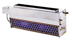
Refrigerant based Fan-Coil Unit. Other variants utilize a chilled, or heated water loop for space cooling, or heating, respectively.


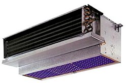
A fan coil unit (FCU), also known as a Vertical Fan Coil Unit (VFCU), is a device consisting of a heat exchanger (coil) and a fan. FCUs are commonly used in HVAC systems of residential, commercial, and industrial buildings that use ducted split air conditioning or central plant cooling. FCUs are typically connected to ductwork and a thermostat to regulate the temperature of one or more spaces and to assist the main air handling unit for each space if used with chillers. The thermostat controls the fan speed and/or the flow of water or refrigerant to the heat exchanger using a control valve.

Due to their simplicity, flexibility, and easy maintenance, fan coil units can be more economical to install than ducted 100% fresh air systems (VAV) or central heating systems with air handling units or chilled beams. FCUs come in various configurations, including horizontal (ceiling-mounted) and vertical (floor-mounted), and can be used in a wide range of applications, from small residential units to large commercial and industrial buildings.

Noise output from FCUs, like any other form of air conditioning, depends on the design of the unit and the building materials surrounding it. Some FCUs offer noise levels as low as NR25 or NC25.

The output from an FCU can be established by looking at the temperature of the air entering the unit and the temperature of the air leaving the unit, coupled with the volume of air being moved through the unit. This is a simplistic statement, and there is further reading on sensible heat ratios and the specific heat capacity of air, both of which have an effect on thermal performance.

Design and operation

[edit]

Fan Coil Unit covers a range of products and will mean different things to users, specifiers, and installers in different countries and regions, particularly in relation to product size and output capability.

Fan Coil Unit falls principally into two main types: blow through and draw through. As the names suggest, in the first type the fans are fitted behind the heat exchanger, and in the other type the fans are fitted in front the coil such that they draw air through it. Draw through units are considered thermally superior, as ordinarily they make better use of the heat exchanger. However they are more expensive, as they require a chassis to hold the fans whereas a blow-through unit typically consists of a set of fans bolted straight to a coil.

A fan coil unit may be concealed or exposed within the room or area that it serves.

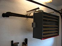
An exposed fan coil unit may be wall-mounted, freestanding or ceiling mounted, and will typically include an appropriate enclosure to protect and conceal the fan coil unit itself, with return air grille and supply air diffuser set into that enclosure to distribute the air.

A concealed fan coil unit will typically be installed within an accessible ceiling void or services zone. The return air grille and supply air diffuser, typically set flush into the ceiling, will be ducted to and from the fan coil unit and thus allows a great degree of flexibility for locating the grilles to suit the ceiling layout and/or the partition layout within a space. It is quite common for the return air not to be ducted and to use the ceiling void as a return air plenum.

The coil receives hot or cold water from a central plant, and removes heat from or adds heat to the air through heat transfer. Traditionally fan coil units can contain their own internal thermostat, or can be wired to operate with a remote thermostat. However, and as is common in most modern buildings with a Building Energy Management System (BEMS), the control of the fan coil unit will be by a local digital controller or outstation (along with associated room temperature sensor and control valve actuators) linked to the BEMS via a communication network, and therefore adjustable and controllable from a central point, such as a supervisors head end computer.

Fan coil units circulate hot or cold water through a coil in order to condition a space. The unit gets its hot or cold water from a central plant, or mechanical room containing equipment for removing heat from the central building's closed-loop. The equipment used can consist of machines used to remove heat such as a chiller or a cooling tower and equipment for adding heat to the building's water such as a boiler or a commercial water heater.

Hydronic fan coil units can be generally divided into two types: Two-pipe fan coil units or four-pipe fan coil units. Two-pipe fan coil units have one supply and one return pipe. The supply pipe supplies either cold or hot water to the unit depending on the time of year. Four-pipe fan coil units have two supply pipes and two return pipes. This allows either hot or cold water to enter the unit at any given time. Since it is often necessary to heat and cool different areas of a building at the same time, due to differences in internal heat loss or heat gains, the four-pipe fan coil unit is most commonly used.

Fan coil units may be connected to piping networks using various topology designs, such as "direct return", "reverse return", or "series decoupled". See ASHRAE Handbook "2008 Systems & Equipment", Chapter 12.

Depending upon the selected chilled water temperatures and the relative humidity of the space, it's likely that the cooling coil will dehumidify the entering air stream, and as a by product of this process, it will at times produce a condensate which will need to be carried to drain. The fan coil unit will contain a purpose designed drip tray with drain connection for this purpose. The simplest means to drain the condensate from multiple fan coil units will be by a network of pipework laid to falls to a suitable point. Alternatively a condensate pump may be employed where space for such gravity pipework is limited.

The fan motors within a fan coil unit are responsible for regulating the desired heating and cooling output of the unit. Different manufacturers employ various methods for controlling the motor speed. Some utilize an AC transformer, adjusting the taps to modulate the power supplied to the fan motor. This adjustment is typically performed during the commissioning stage of building construction and remains fixed for the lifespan of the unit.

Alternatively, certain manufacturers employ custom-wound Permanent Split Capacitor (PSC) motors with speed taps in the windings. These taps are set to the desired speed levels for the specific design of the fan coil unit. To enable local control, a simple speed selector switch (Off-High-Medium-Low) is provided for the occupants of the room. This switch is often integrated into the room thermostat and can be manually set or automatically controlled by a digital room thermostat.

For automatic fan speed and temperature control, Building Energy Management Systems are employed. The fan motors commonly used in these units are typically AC Shaded Pole or Permanent Split Capacitor motors. Recent advancements include the use of brushless DC designs with electronic commutation. Compared to units equipped with asynchronous 3-speed motors, fan coil units utilizing brushless motors can reduce power consumption by up to 70%.[1]

Fan coil units linked to ducted split air conditioning units use refrigerant in the cooling coil instead of chilled coolant and linked to a large condenser unit instead of a chiller. They might also be linked to liquid-cooled condenser units which use an intermediate coolant to cool the condenser using cooling towers.

DC/EC motor powered units

[edit]

These motors are sometimes called DC motors, sometimes EC motors and occasionally DC/EC motors. DC stands for direct current and EC stands for electronically commutated.

DC motors allow the speed of the fans within a fan coil unit to be controlled by means of a 0-10 Volt input control signal to the motor/s, the transformers and speed switches associated with AC fan coils are not required. Up to a signal voltage of 2.5 Volts (which may vary with different fan/motor manufacturers) the fan will be in a stopped condition but as the signal voltage is increased, the fan will seamlessly increase in speed until the maximum is reached at a signal Voltage of 10 Volts. fan coils will generally operate between approximately 4 Volts and 7.5 Volts because below 4 Volts the air volumes are ineffective and above 7.5 Volts the fan coil is likely to be too noisy for most commercial applications.

The 0-10 Volt signal voltage can be set via a simple potentiometer and left or the 0-10 Volt signal voltage can be delivered to the fan motors by the terminal controller on each of the Fan Coil Units. The former is very simple and cheap but the latter opens up the opportunity to continuously alter the fan speed depending on various external conditions/influences. These conditions/criteria could be the 'real time' demand for either heating or cooling, occupancy levels, window switches, time clocks or any number of other inputs from either the unit itself, the Building Management System or both.

The reason that these DC Fan Coil Units are, despite their apparent relative complexity, becoming more popular is their improved energy efficiency levels compared to their AC motor-driven counterparts of only a few years ago. A straight swap, AC to DC, will reduce electrical consumption by 50% but applying Demand and Occupancy dependent fan speed control can take the savings to as much as 80%. In areas of the world where there are legally enforceable energy efficiency requirements for fan coils (such as the UK), DC Fan Coil Units are rapidly becoming the only choice.

Areas of use

[edit]


In high-rise buildings, fan coils may be vertically stacked, located one above the other from floor to floor and all interconnected by the same piping loop.

Fan coil units are an excellent delivery mechanism for hydronic chiller boiler systems in large residential and light commercial applications. In these applications the fan coil units are mounted in bathroom ceilings and can be used to provide unlimited comfort zones - with the ability to turn off unused areas of the structure to save energy.

Installation

[edit]

In high-rise residential construction, typically each fan coil unit requires a rectangular through-penetration in the concrete slab on top of which it sits. Usually, there are either 2 or 4 pipes made of ABS, steel or copper that go through the floor. The pipes are usually insulated with refrigeration insulation, such as acrylonitrile butadiene/polyvinyl chloride (AB/PVC) flexible foam (Rubatex or Armaflex brands) on all pipes, or at least on the chilled water lines to prevent condensate from forming.

Unit ventilator

[edit]

A unit ventilator is a fan coil unit that is used mainly in classrooms, hotels, apartments and condominium applications. A unit ventilator can be a wall mounted or ceiling hung cabinet, and is designed to use a fan to blow outside air across a coil, thus conditioning and ventilating the space which it is serving.

European market

[edit]

The Fan Coil is composed of one quarter of 2-pipe-units and three quarters of 4-pipe-units, and the most sold products are "with casing" (35%), "without casing" (28%), "cassette" (18%) and "ducted" (16%).[2]

The market by region was split in 2010 as follows:

Region Sales Volume in units[2] Share
Benelux 33 725 2.6%
France 168 028 13.2%
Germany 63 256 5.0%
Greece 33 292 2.6%
Italy 409 830 32.1%
Poland 32 987 2.6%
Portugal 22 957 1.8%
Russia, Ukraine and CIS countries 87 054 6.8%
Scandinavia and Baltic countries 39 124 3.1%
Spain 91 575 7.2%
Turkey 70 682 5.5%
UK and Ireland 69 169 5.4%
Eastern Europe 153 847 12.1%

See also

[edit]
  • Thermal insulation
  • HVAC
  • Construction
  • Intumescent
  • Firestop

References

[edit]
  1. ^ "Fan Coil Unit". Heinen & Hopman. Retrieved 2023-08-30.
  2. ^ a b "Home". Eurovent Market Intelligence.


Room air distribution is characterizing how air is introduced to, flows through, and is removed from spaces.[1] HVAC airflow in spaces generally can be classified by two different types: mixing (or dilution) and displacement.

Mixing systems

[edit]

Mixing systems generally supply air such that the supply air mixes with the room air so that the mixed air is at the room design temperature and humidity. In cooling mode, the cool supply air, typically around 55 °F (13 °C) (saturated) at design conditions, exits an outlet at high velocity. The high-velocity supply air stream causes turbulence causing the room air to mix with the supply air. Because the entire room is near-fully mixed, temperature variations are small while the contaminant concentration is fairly uniform throughout the entire room. Diffusers are normally used as the air outlets to create the high-velocity supply air stream. Most often, the air outlets and inlets are placed in the ceiling. Supply diffusers in the ceiling are fed by fan coil units in the ceiling void or by air handling units in a remote plant room. The fan coil or handling unit takes in return air from the ceiling void and mix this with fresh air and cool, or heat it, as required to achieve the room design conditions. This arrangement is known as 'conventional room air distribution'.[2]

Outlet types

[edit]
  • Group A1: In or near the ceiling that discharge air horizontally[3]
  • Group A2: Discharging horizontally that are not influenced by an adjacent surface[3]
  • Group B: In or near the floor that discharge air vertically in a linear jet[3]
  • Group C: In or near the floor that discharge air vertically in a spreading jet[3]
  • Group D: In or near the floor that discharge air horizontally[3]
  • Group E: Project supply air vertically downward[3]

Displacement ventilation

[edit]

Displacement ventilation systems supply air directly to the occupied zone. The air is supplied at low velocities to cause minimal induction and mixing. This system is used for ventilation and cooling of large high spaces, such as auditorium and atria, where energy may be saved if only the occupied zone is treated rather than trying to control the conditions in the entire space.

Displacement room airflow presents an opportunity to improve both the thermal comfort and indoor air quality (IAQ) of the occupied space. It also takes advantage of the difference in air density between an upper contaminated zone and a lower clean zone. Cool air is supplied at low velocity into the lower zone. Convection from heat sources creates vertical air motion into the upper zone where high-level return inlets extract the air. In most cases these convection heat sources are also the contamination sources (e.g., people, equipment, or processes), thereby carrying the contaminants up to the upper zone, away from the occupants.

The displacement outlets are usually located at or near the floor with the air supply designed so the air flows smoothly across the floor. Where there is a heat source (such as people, lighting, computers, electrical equipment, etc.) the air will rise, pulling the cool supply air up with it and moving contaminants and heat from the occupied zone to the return or exhaust grilles above. By doing so, the air quality in the occupied zone is generally superior to that achieved with mixing room air distribution.

Since the conditioned air is supplied directly into the occupied space, supply air temperatures must be higher than mixing systems (usually above 63 °F or 17 °C) to avoid cold draughts at the floor. By introducing the air at supply air temperatures close to the room temperature and low outlet velocity a high level of thermal comfort can be provided with displacement ventilation.

See also

[edit]
  • Dilution (equation)
  • Duct (HVAC)
  • HVAC
  • Lev door
  • Underfloor air distribution
  • Indoor air quality
  • Thermal comfort
  • Air conditioning
  • ASHRAE
  • SMACNA

References

[edit]
  1. ^ Fundamentals volume of the ASHRAE Handbook, Atlanta, GA, USA, 2005
  2. ^ Designer's Guide to Ceiling-Based Room Air Diffusion, Rock and Zhu, ASHRAE, Inc., Atlanta, GA, USA, 2002
  3. ^ a b c d e f ASHRAE Handbook: Fundamentals, 2021


Photo
Photo
Photo
Photo
Photo
Photo

Driving Directions in Jefferson County


Driving Directions From Fenton Sew and Vac to Royal Supply Inc
Driving Directions From JCPenney to Royal Supply Inc
Driving Directions From Stella Blues Vapors to Royal Supply Inc
Driving Directions From Target to Royal Supply Inc
Driving Directions From Visit Jefferson County PA to Royal Supply Inc
Driving Directions From Jefferson Historical Museum to Royal Supply Inc
Driving Directions From Jefferson Landing State Historic Site to Royal Supply Inc
Driving Directions From Jefferson Barracks Park to Royal Supply Inc
Driving Directions From Jefferson Historical Museum to Royal Supply Inc
Driving Directions From Cole County Historical Museum to Royal Supply Inc

Reviews for Royal Supply Inc


Royal Supply Inc

Toney Dunaway

(5)

This is another amazing place where we will do much more business. They are not tyrannical about the totally useless face diapers, they have a great selection of stock, they have very knowledgeable staff, very friendly staff. We got the plumbing items we really needed and will be getting more plumbing items. They also have central units, thermostats, caulking, sealants, doors, seems everything you need for a mobile home. We've found a local treasure and will be bringing much more business. Their store is clean and tidy as well!

Royal Supply Inc

Gidget McCarthy

(5)

Very knowledgeable, friendly, helpful and don't make you feel like you're inconveniencing them. They seem willing to take all the time you need. As if you're the only thing they have to do that day. The store is clean, organized and not cluttered, symmetrical at that. Cuz I'm even and symmetricals biggest fan. It was a pleasure doing business with them and their prices are definitely reasonable. So, I'll be doing business with them in the future no doubt.

Royal Supply Inc

bill slayton

(1)

Went to get a deadbolt what they had was one I was told I'd have take it apart to lengthen and I said I wasn't buying something new and have to work on it. Thing of it is I didn't know if it was so that it could be lengthened said I didn't wanna buy something new I had to work on just to fit my door. He got all mad and slung the whole box with part across the room. A real business man. I guess the owner approves of his employees doing as such.

Royal Supply Inc

Ae Webb

(5)

Royal installed a new furnace and air conditioner just before we got our used mobile home. Recently, the furnace stopped lighting. Jared (sp?) made THREE trips to get it back to good. He was so gracious and kind. Fortunately for us it was still under warranty. BTW, those three trips were from Fenton, Missouri to Belleville, Illinois! Thanks again, Jared!

Royal Supply Inc

Terry Self

(1)

Horrible workmanship, horrible customer service, don't show up when they say they are. Ghosted. Was supposed to come back on Monday, no call no show. Called Tuesday and Wednesday, left messages both days. Nothing. Kinked my line, crooked to the pad and house, didn't put disconnect back on, left the trash.....

View GBP

Frequently Asked Questions

To identify leaks in duct connections, visually inspect the ducts for any obvious gaps, tears, or disconnections. You can also use a smoke pencil or incense stick to detect air movement around connections while the system is running. Additionally, listening for unusual noises like whistling when the HVAC is operational can indicate leakage.
To seal leaks effectively, you will need mastic sealant or foil-backed tape specifically designed for ductwork. Avoid using standard duct tape as it deteriorates over time. A brush or applicator will be needed for the mastic sealant, and a pair of scissors may be useful when working with tape.
Yes, common areas prone to leakage include joints and seams where sections of ductwork connect, particularly around bends and branches. Any area where ducts meet vents or registers should also be checked closely, as these junctions often have loose fittings that can lead to air loss.